Ok, there a couple of options here.
The picture of the hacking page shows another chip below the memory part. The control lines from the edge connector to go to that, then that device connectst to the memory part.
If we can determine what that part is you can probably get by with a simpler solution, likely serial read/writes, and that part acts as shift register/memory to capture the address & data to be written, or buffers the data read back to be read out serially.
If not, then another option is to attach 18 wires and bring those to a connector such as this
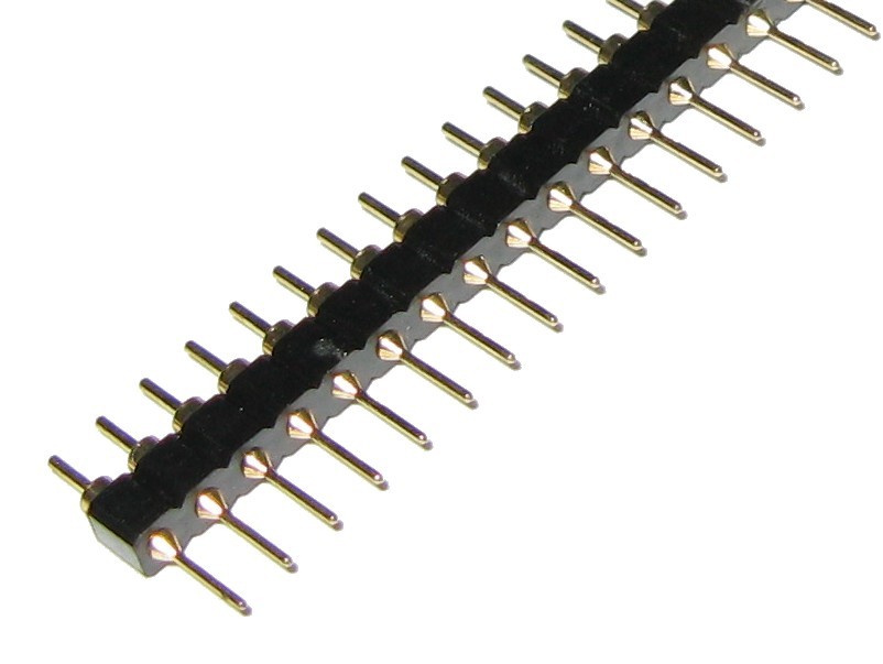
that you can than plug into a breadboard, and add your own 5v to 3.3v level converters.
Then you can connect to 8 I/O lines from your arduino and 8 control/status lines and power/gnd, and remove the magic gate part and the other part and contol the memory part directly.
To make it easier to start, you could use a part like a 8 MHz/3.3V promini, or wire up your own equivalent on the breadboard (just need a 328, 8 MHz crystal, two 22 pF caps, 10K resister, totals around a dollar at dipmicro), and a 3.3V FTDI Basic from Gravitech
to handle the PC interface for downloading sketches and create 3.3V for you.
The hardware setup is pretty straightforward. Attaching the wires could be tricky, get a good soldering iron and be patient.
The software, there are several modes to be supported. You will probably write a function per mode, the function will take in the address to be accessed, and data to be written, and manage the application of the control signals, check the status signals, etc.
If you can post high resolution, clear, pictures of both sides of the card, we can see if using the onboard buffer would be possible.


