Would some of you reading this mind looking over my wiring diagrams and check I have everything correct.
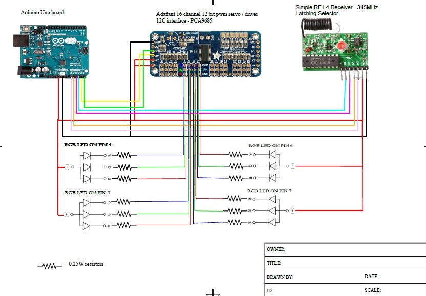
Diagram 1 - Wiring Diagram 1:
I have taken the wiring up from the datasheets / guides from the individual products and (hopefully) created the correct
wiring setup so that everything will work.
To power all of this I will be using a battery pack that is 7.5V and 3380MAh. I know I will need a voltage stepper downer to get down to 5V ... but I don't yet know what that is or how it would fit into the circuit.
On the 16 channel board, each of the pins numbered 4,5,6 and 7 will be operating a set of 12 RGB LED's (I have only included one RGB LED per pin on the main drawing for the sake of clarity).
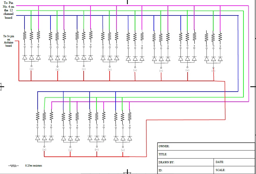
Diagram 2 - RGB LED group Wiring 1:
This is an extension diagram showing the twelve RGB LED's wired up to pin No. 4 on the 12 channel board shown on the first diagram.
The 5V line is the one from the Arduino Uno board.
In you opinions, is this an efficient way to wire up the RGB LEDS?
Thank you for your time and any advice or corrections you are able to offer.
Probably a good idea to add an electrolytic capacitor on the PWM servo driver board. There's a label on the board that marks the position where it's supposed to go.
Southpark:
Probably a good idea to add an electrolytic capacitor on the PWM servo driver board. There's a label on the board that marks the position where it's supposed to go.
Useless.
C2 is connected to the servo supply, that is not used here.
Leo..
Why an RF receiver with decoder and latching outputs connected to analogue inputs.
A simple RF receiver and the decoding done by the Arduino is more flexible.
Note that here is a 400mA current limit and 400mA power limit for the PCA9685 chip.
12 RBG LEDs might be to much (depending on resistor values).
As LarryD already said. Why don't you use addressable LEDs.
Leo..
When I started looking at options for this project, initially I wanted to use Neo-pixel rings. I was advised that due to the length of wire needed from the control boards to each of the 4 separate pods, neo pixels would run out of power.
I have attached a quick diagram of the prop I am attempting to build.
The base is 1.5 metres (150 cm) long.
Each of the uprights is 1m (100 cm) high
One group of 12 LEDS are contained in each of the 'pods' at the top each upright.
From the control boards located in the base, I would need to run 3 cables from each pin (the R,G,B) to each pod. Plus one cable from the +5v in a circuit from the control boards, up and down each upright / pod.
What I am attempting to build is a prop that has four uprights on a base. At the top of each upright is a pod with lighting inside.
At the start, each pod is off. With the press of a button on a key fob each pod will light up in a different colour. As an example 1st one red, 2nd one Blue, 3rd one Green and the 4th one Pink.
With the press of a second button on the remote, I'd like the pods to run a basic light chase program where the lights run in a sequence from left to right ie the red (starting in pod 1) moves from pod 1 to 2 to 3 to 4 and repeats. The Blue (starts in pod 2) runs from pod 2 to 3 to 4 to 1 and repeats etc
"Why an RF receiver with decoder and latching outputs connected to analogue inputs.
A simple RF receiver and the decoding done by the Arduino is more flexible."
I was under the impression that the Uno board could only run 2 independent RGB leds as there are only 6 pwm pins. With the 12 channel board I can run 4 independant rgb leds.
The latching receiver is to switch and keep the next program running when a button is pressed and let go.
I hope I'm making sense.... I'm confusing myself now.
damian_jay:
I was advised that due to the length of wire needed from the control boards to each of the 4 separate pods, neo pixels would run out of power.
The latching receiver is to switch and keep the next program running when a button is pressed and let go.
Seems rubbish. Could you link to that post.
You should ofcourse calculate wire size/resistance before building.
Latching could also be done in software.
You could use multiple keyfobs for even more patterns if you use software decoding.
Leo..
When I started looking at options for this project, initially I wanted to use Neo-pixel rings. I was advised that due to the length of wire needed from the control boards to each of the 4 separate pods, neo pixels would run out of power.
I think you have the wrong end of the stick here - its the signal to the neopixels that won't tolerate
driving a long wire since its a high speed clock and you risk signal reflections and degradation. Power
distribution is simple, use thick enough wires! The signal issue is compounded by the need to string all
the neopixels linearly, so the signal path would need to thread between all 4 pods.
I don't understand why you are using a servo driver to power lots of LEDS, it has no special current
driving ability, you could probably drive one ot two LEDs per channel. You seem to be using a dozen or
more LEDs per channel, so perhaps 0.3A per channel is needed?
MarkT:
I think you have the wrong end of the stick here - its the signal to the neopixels that won't tolerate
driving a long wire since its a high speed clock and you risk signal reflections and degradation. Power
distribution is simple, use thick enough wires! The signal issue is compounded by the need to string all
the neopixels linearly, so the signal path would need to thread between all 4 pods.
Thank you, is there a way of boosting the signal after each pod?
MarkT:
I don't understand why you are using a servo driver to power lots of LEDS, it has no special current
driving ability, you could probably drive one ot two LEDs per channel. You seem to be using a dozen or
more LEDs per channel, so perhaps 0.3A per channel is needed?
The servo driver (I'm guessing that's the 16 channel PWM part) is used to drive 4 sets of 'RGB LED pods' independently of each other so each pod can be a different colour.
I was advised to use this add on board (16 channel) as the Uno only has enough PWM pins to drive two pods.
I am getting very confused with this lol.
Possibly the easiest thing for me to do would be to put a post in the Project part of the forum, detailing what I would like to achieve and ask for people's input. The advice I've been getting just seems to be geared towards selling more parts that I may or may not need.