zoomkat:
"Where would I start with this? Is this even a realistic aim?"
2.5.B2 Moving an Immediate Data into a Memory Location
Engineers engage hell of efforts to consolidate their understandings (acquired using suitable Learning Kit: MicroTalk-8086) within pictures which they later on disclose in the public domain.
Instruction:       mov BYTE PTR ds:[bx+10h], 45h

Coding:
01000 (0000:1000) - mov BYTE PTR ds:[bx+10h], 45h : C6 47 10 45
Meaning: The data for the destination memory location comes from a memory location (immediate addressing mode), which just follows the location (s) that holds the opcode bytes (instruction bytes).
Assume that ds = 0000h, bx=3000h and then 45h would be stored at location 03010h
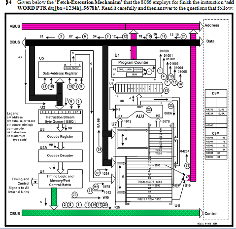
Fetch-Execution: Shown below in Fig-2.45.
Figure-2.45: Explaining Fetch-Execution Mechanism of ‘mov BYTE PTR ds:[bx+10h], 45h’ Instruction
1. The PC (Program Counter, U1) asserts the address 01000h on the address bus.
2. The CM (Control Matrix, U4) sends the RD/-signal to the memory chip.
3. The opcode C6 (content of CSM memory location 01000h) enters into the opcode decoder. The opcode is interpreted and the CM understands that current instruction has an opcode of two bytes long.
4. The CM increments the PC, which is now 01001h. The address is put on the ABUS.
5. The CM generates the next RD/-signal.
6. The opcode 47 (content of the memory location 01001h) enters into opcode decoder. The opcodes ‘C6 47’ are jointly decoded and the CM extracts the following information:
i. The current instruction is 4-byte long. Therefore, two more read operations must be carried out to bring the remaining two byes (10 45) information from the memory.
ii. Addressing Mode is determined as ‘Immediate’, which means that the last information byte (45) is the data for the destination.
7. The CM increments the PC, which is now 01002h. The address is put on the ABUS.
8. The CM generates the RD/-signal.
9. The data 10h (8-bit displacement) enters into the DAR from where it enters into TRA8 of U7.
10. The CM increments the PC, which is now 01003h. The address is put on the ABUS.
11. The CM generates the RD/-signal.
12. The data byte 45h comes from the CSM and then enters into the TRB8 of U7.
13. The content of ds, bx and TRA8 are added together to get the destination memory address as: 03010h. The resultant address is asserted on the ABUS.
14. The contents of TRB8 (45) is placed on the DBUS.
15. The CM sends data write signal to the memory chip. The data byte 45h enters into the DSM location: 03010h.
The above-mentioned 15 steps are required to accomplish the task defined by the instruction:
mov BYTE PTR ds:[bx+10h], 45h. The instruction execution cycle consists of:
i. Four read operations (1-3, 4-6, 7-9 and 10-12).
ii. One write operation, which occurs in the background.


")