Hello, I would like to know if this circuit is connected correctly. The stepper motor is a NEMA17 model, and the motor driver is an A4988 with an driver board. I would like to connect the linear actuator using a 2-channel relay. Both the motor and the actuator operate on 12V input voltage. And I need to add a wind speed sensor that operates on 12V to this circuit.
I've already broken two Arduino boards. I really need your help to make sure everything is connected properly.
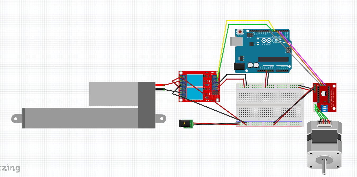
Sorry I cannot follow your picture. Posting an annotated schematic would be much better. This might help:
Gil's Crispy Critter Rules for Processor Hardware:
- Rule #1: An Arduino is NOT a Power Supply!
- Rule #2: Never connect anything inductive (motors, speakers) directly to an Arduino!
- Rule #3: Avoid connecting or disconnecting wires while the power is on.
- Rule #4: Do not apply power to any pin unless you are certain of what you're doing.
- Rule #5: Do not exceed the maximum voltage ratings.
- Rule #6: Many Arduinos cannot power transmitters directly.
- Rule #7: Before powering your project, take a break and double-check the wiring.
LaryD’s Corollaries:
- Coro #1: When starting out, add a 220Ω resistor in series with both input and output pins to protect against shorts.
- Coro #2: Invest in a Digital Multi-Meter (DMM) to measure voltages, currents, and resistance.
Note: Violating these rules can turn your Arduinos into crispy critters. For optimal performance, keep your wires under 25 cm (10 inches).
Additional Tips:
- The L293 motor driver, though common, is inefficient as it can lose around 3V as heat when driving both legs of a motor. Consider using a motor driver with MOSFET outputs to reduce heat loss and conserve battery power.
- For more on powering Arduino boards, explore this guide: Powering Alternatives for Arduino Boards.
Why not to use motor driver for that as well.
Likely no-one can give you more than guesses if you don post the specs of your motors and power supplies.
Is your Arduino board a genuine Arduino UNO R3 (as per your diagram), and how are you supplying power to the Arduino (no power source seems to be included in your diagram)?
Here are specs.
Motor Specifition:

Linear actuator Specifition:
-Operating Voltage: 12V
- Stroke Length: 50mm
- Maximum Speed: 12mm/s (no-load stroke)
- This is the maximum speed; actual speed may vary depending on the load.
- Maximum Load (Force): 100 Kgf·m
- Duty Cycle: S2 – 10 minutes
- IP Rating: IP66
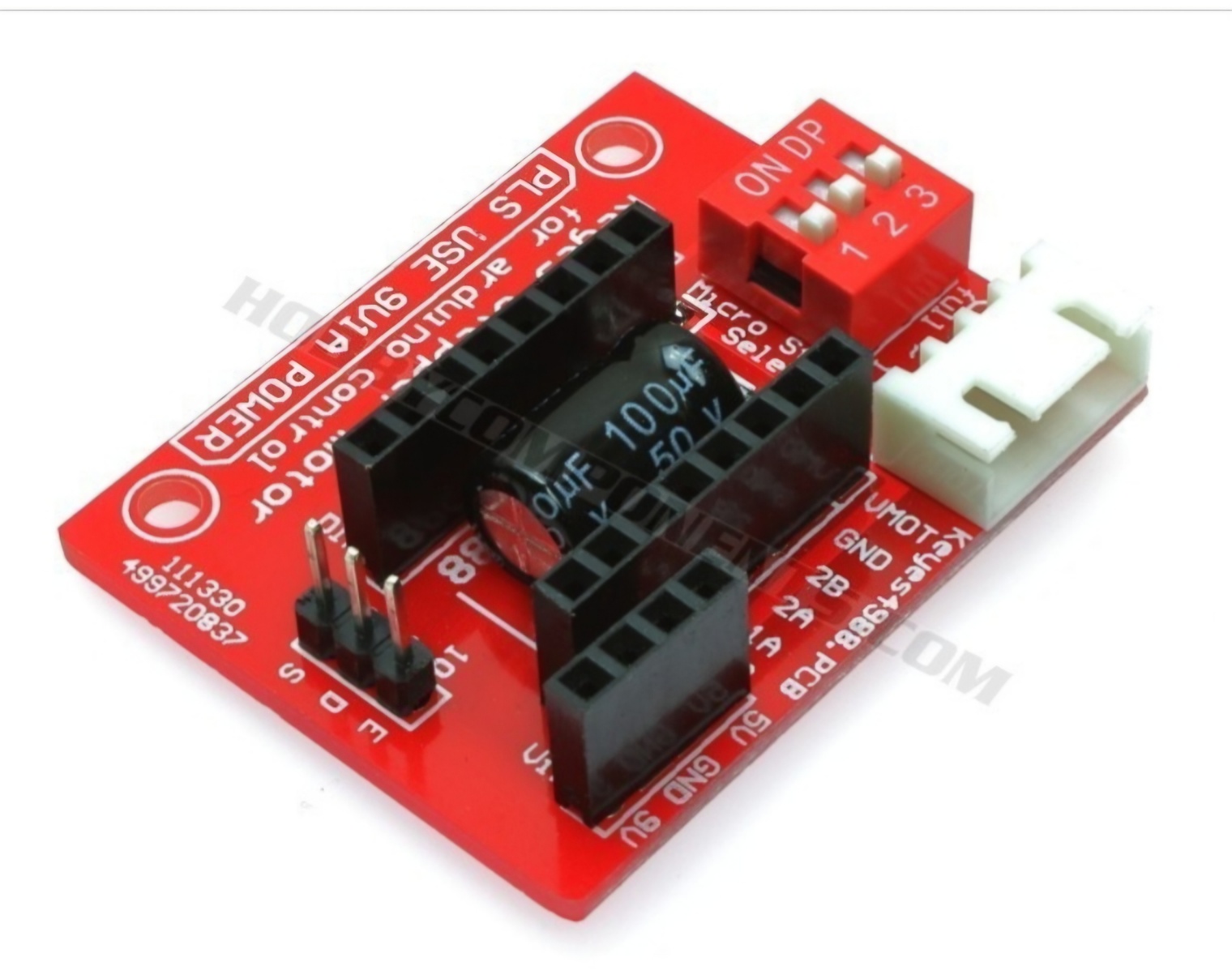
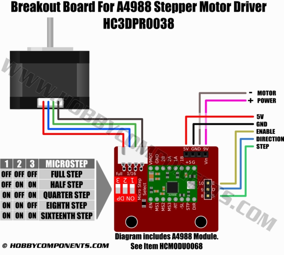
A4988 motor driver board
I’m using a relay because the linear actuator only needs to be activated once and then turned off. For the power supply, I will use three 3.6V, 3.6A lithium batteries.
And where is the 5V supply?
Also, some more specific info about your battery setup would help here.
The A4988 driver can deliver only 1 A/phase without overheating, so be sure to set the current limit correctly.
The linear actuator will briefly draw the start/stall current every time it starts moving, typically 5 to 10 Amperes for 12V actuators. The power supply must be able to deliver more than that.
Breadboards cannot handle motor currents. The tracks will burn, so leave it out of the project. Solder all power leads or use screw terminals if provided.
Could you please explain what the 5V battery is used for? The battery has a rated voltage of 3.6V and a capacity of 3.6A. It is a rechargeable lithium battery. I couldn’t find the exact datasheet. The linear actuator is working properly with the battery power.
Ok. I’ll proceed without using a breadboard. And the only battery I have on hand is a 3.6V rechargeable lithium cell. Could you check if there are any incorrect connections in the circuit? Are all the GND lines properly connected?
Thank you for your advice:)
What is that for? The motor driver and the linear actuator require 12V at several Amperes.
Forum members strongly recommend to get one part of the project working at a time, and when all of them work perfectly, then start adding the pieces together, debugging as you go.