I have two 2.4" boards like your one. One says T_DO and the other says T_OUT.
Your photo looks wrong to me. Perhaps this is a better diagram:
- + A B C D E | F G H I J
|
oT_IRQ |
MISO----oT_OUT |
MOSI----oT_DIN |
SCK----oT_CLK |
o-----10k-----o oT_CS o---4k7---o o---------->D3
o oMISO o---4k7---o o---------->D12
o--------------o oLED
o-----10k-----o o oSCK o---4k7---o o---------->D13
o-----10k-----o o oMOSI o---4k7---o o---------->D11
o-----10k-----o oDC o---4k7---o o---------->D9
o-----10k-----o oRST o---4k7---o o---------->D8
o-----10k-----o oCS o---4k7---o o---------->D10
o------------------o oGND -o---------o o---------->GND
o--------------o oVCC o---------o o---------->5V
|
|
|
The 10k plug between GND (-) column and column B
The 4k7 plug between column E and column G i.e. across the V notch
The link wires from T_OUT, T_DIN, T_CLK, LED can go in column C
The display plugs into column D
Run flying leads to the Uno.
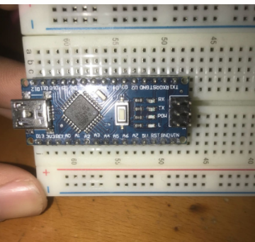
Much easier with a 3.3V Arduino. You just have straight wires to the Zero or Due.
I suggest that you omit the Touch jumper wires for the moment.
Just get the resistors correct for the TFT screen.
Then you can run regular examples from the Adafruit_ILI9341 library with this constructor:
Adafruit_ILI9341 tft(10, 9, 8);
I have run and tested programs on my similar TFT and Touchscreen.
When the TFT is working you can add the jumper wires on column C to enable the TouchScreen.
I am no good with cameras. Otherwise I could show you photos instead of diagrams.
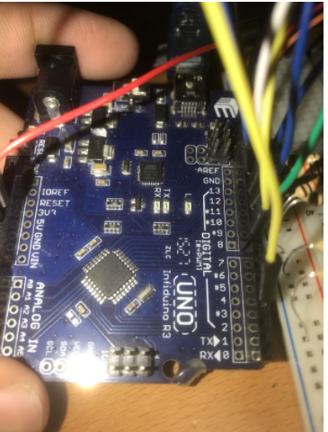
Mind you, I can not identify the colour bands on your resistors from the photo.
David.
Edit. I have improved my diagram. Shows the columns better. To show where to insert wire links or resistors.