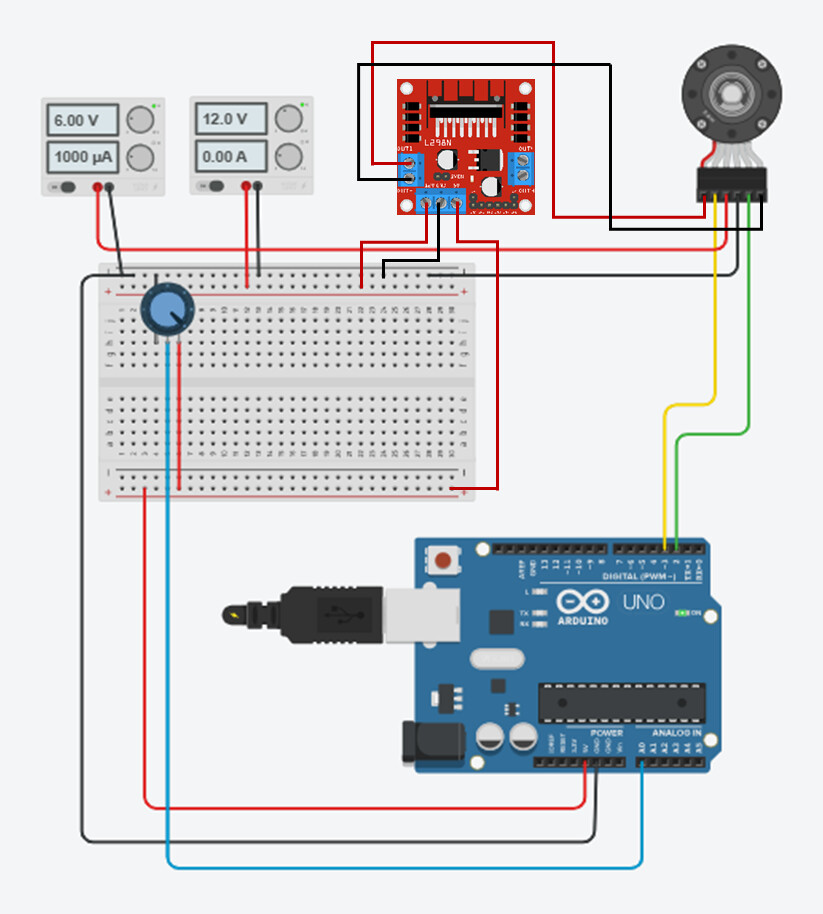
I am using an N20B DC motor with an encoder to measure speed, an L298N motor driver for control, and a potentiometer to adjust the motor speed.
I want to display the voltage and speed curves on the Serial Plotter. The speed will change by adjusting the voltage using a potentiometer, demonstrating a first-order system response. From these curves, I aim to derive the transfer function, such as Kτs+1\frac{K}{\tau s + 1}τs+1K.
Additionally, I would like to know how to determine in the code the motor's encoder pulses per revolution (e.g., encoderPPR = 12) and set the measurement interval (e.g., interval = 100 ms).
I used the code below,
#define ENA 5   // PWM pin for motor speed control
#define IN1 9   // Motor driver IN1
#define IN2 10  // Motor driver IN2
#define ENC_A 2 // Encoder signal A (interrupt pin)
#define ENC_B 3 // Encoder signal B
#define POT A0  // Potentiometer for adjusting voltage

volatile long encoderCount = 0; // Encoder pulse count
float rpm = 0;                 // Motor speed in RPM
unsigned long lastTime = 0;

const int encoderPPR = 12;      // Pulses per revolution of the encoder
const int gearRatio = 150;       // Gear ratio of the motor
const int effectivePPR = encoderPPR * gearRatio; // Effective PPR for the output shaft
const int interval = 100;        // Time interval for RPM calculation (ms)

// Interrupt service routine for encoder signal
void readEncoder() {
  if (digitalRead(ENC_B) == HIGH) {
    encoderCount++; // Increment count for forward rotation
  } else {
    encoderCount--; // Decrement count for reverse rotation
  }
}

void setup() {
  // Motor driver pins
  pinMode(ENA, OUTPUT);
  pinMode(IN1, OUTPUT);
  pinMode(IN2, OUTPUT);

  // Encoder pins
  pinMode(ENC_A, INPUT_PULLUP);
  pinMode(ENC_B, INPUT_PULLUP);

  // Attach interrupt for encoder signal
  attachInterrupt(digitalPinToInterrupt(ENC_B), readEncoder, RISING);

  // Initialize serial communication
  Serial.begin(9600); // For Arduino Serial Plotter
}

void loop() {
  // Read potentiometer value (0-1023)
  int potValue = analogRead(POT);

  // Map potentiometer value to PWM (0-255) and calculate input voltage
  int pwmValue = map(potValue, 0, 1023, 0, 255);
  float inputVoltage = (potValue * 6.0) / 1023.0; // Convert to voltage (assuming 6V reference)

  // Apply PWM to motor driver
  analogWrite(ENA, pwmValue);
  digitalWrite(IN1, HIGH); // Motor forward direction (Encoder rotate clockwise)
  digitalWrite(IN2, LOW);

  // Calculate RPM
  unsigned long currentTime = millis();
  if (currentTime - lastTime >= interval) { // Every `interval` ms
    rpm = (encoderCount / (float)effectivePPR) * (60000.0 / interval); // Calculate RPM
    encoderCount = 0; // Reset encoder count
    lastTime = currentTime;

// Plot RPM vs Voltage in Serial Plotter
    Serial.print(inputVoltage); // Plot Voltage
    Serial.print(",");
    Serial.println(rpm);        // Plot RPM
  }
}