Hello, I am looking at the NP50P04SDG PNP Mosfet. It is a logic level device, but I have a quick question. In the datasheet it says the gate to source threshold voltage is about -1.6v. Is that 1.6 volts under source? So if I had 12 volts going in i'd have to give it at least 10.4 to make sure that it's off? The 0volts would make the mosfet turn on. Am I thinking right here?
Thanks, Mike
Yep, looks logical. For negative ground PSU
What is the purpose of calling it logic level then? Just because it is less than 5 volts difference from the source? Also, do I need a resistor on the gate line, or can I just connect it to source to turn it off and 0v to turn it on?
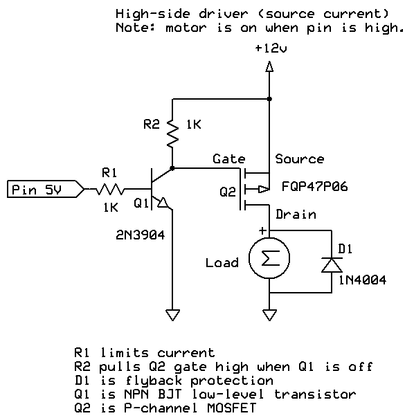
Use a gate resistor and more, you will need an NPN transistor to pull down the gate... Turn on occurs when the gate becomes 1.6V Lower Than the Source. If you connect the gate to an Arduino output it will never turn off. you will need some kind of small signal transistor like a 2N3904 or 2N2222 1 4K7 resistors and a 10K resistor. Ground the emitter of the NPN, connect to base to the Arduino output through one of the resistors. Connect the Collector through the other resistor 4K7 resistor to the P-Ch Fet gate and connect the 10K resistor from the gate to +12V source along with the Source lead of the P-Ch Fet. Now when the Arduino output pin is high the drain will be at +12V with a lot of available.
Doc
I understand the Arudino can not turn it back off once it comes on with out addition hardware. I'm just trying to get a grasp of what it's looking for. Can I just connect the gate to source to turn it off and ground to turn it on?
If you have the P-channel MOSFET switching 12V on and off, you need a low voltage to turn if On - Arduino low output can certainly do that.
To turn it off tho, you need the gate to go up to 12V - and the arduino can't do that. Hence the need for the NPN transistor set up with an Open Collector output. When the NPN base is low, the NPN is Off, and the resistor can pull the P-channel Gate up to 12V to turn it off without damaging the Arduino, which only expects 5.5V.
To turn it on, the NPN base is driven High, the NPN collector/emitter path opens up, the P-channel gate is pulled down to ~0.7V, and the P-channel is turned on.
mike_r:
What is the purpose of calling it logic level then? Just because it is less than 5 volts difference from the source? Also, do I need a resistor on the gate line, or can I just connect it to source to turn it off and 0v to turn it on?
Logic-level means that the device will act properly as a switch from just 5V of gate drive (for p-channel MOSFET that means -5V on the gate relative to the source). Sometimes logic-level might mean works from 3.3V or less, but in general it means 5V compatible (most power MOSFETs need 10 to 12V to switch fully on). For switching applications its best to ignore the threshold voltage spec, a MOSFET is off when Vgs=0, and on when Vgs is at least the value in the specification for Rds(on). The threshold voltage is highly variable between devices and normally only a useful spec for linear amplification, not switching.
If just connecting the gate directly to 0V or the source no resistor is needed, however if driving it from an Arduino pin a gate resistor is needed to prevent damage (max current 40mA) from the switching transients - although the MOSFET gate takes no current at DC, it has a large capacitance and this causes current spikes as the gate is charged and discharged. 150 ohms will do nicely.
As people have pointed out if you are doing high-side switching of a circuit running from more than 5V, being logic level is irrelevant since the source is not at +5V.
People often add a 10k resistor between the gate and source of the MOSFET to ensure it stays fully off during the period the microcontroller is starting up or during reset.