Pololu High-Power Stepper Motor Driver 36v4 with Arduino MEGA

Hello,
I am trying to use an Arduino MEGA to control a NEMA 17 stepper motor (https://amzn.eu/d/8sh1eRl) with a Pololu 36v4 driver (Pololu High-Power Stepper Motor Driver 36v4). I followed the proposed setup as shown in the typical wiring diagram but moved the pins SDATO, SDATI, SCLK to pins 53, 52, and 51 on the arduino MEGA. I tried to use the BasicStepping example that comes with the arduino library (GitHub - pololu/high-power-stepper-driver-arduino: Arduino library for Pololu High-Power Stepper Motor Drivers) but the motor does not seem to be moving. Around the Vin and GND, I measured 12V but then the driver motor windings don't seem to have any current flowing in them.
Anyone have any idea why this might happen? Is it possible that the arduino mega is not compatible with this driver?

Thanks in advance for the help!

Mega is compatible. Did you set the max current on code?
Instead of writing about your wiring, post a scheme of actual wiring and also post the code you are using.

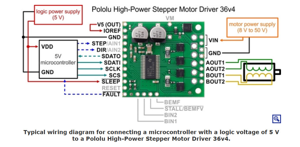
Hi kmin, thanks for the answer. Yes, I have set the max current to 1.4A in the code. This is the scheme of my wiring :


As for the code being used is exactly the example from Basic Stepping apart from small changes to maxcurrent and delays... : ```#include <SPI.h>
#include <HighPowerStepperDriver.h>

const uint8_t DirPin = 2;
const uint8_t StepPin = 3;
const uint8_t CSPin = 4;

// This period is the length of the delay between steps, which controls the
// stepper motor's speed. You can increase the delay to make the stepper motor
// go slower. If you decrease the delay, the stepper motor will go faster, but
// there is a limit to how fast it can go before it starts missing steps.
const uint16_t StepPeriodUs = 2000;

HighPowerStepperDriver sd;

void setup()
{
Serial.print("setting up the driver");
SPI.begin();
sd.setChipSelectPin(CSPin);

// Drive the STEP and DIR pins low initially.
pinMode(StepPin, OUTPUT);
digitalWrite(StepPin, LOW);
pinMode(DirPin, OUTPUT);
digitalWrite(DirPin, LOW);

// Give the driver some time to power up.
delay(1);

// Reset the driver to its default settings and clear latched status
// conditions.
sd.resetSettings();
sd.clearStatus();

// Select auto mixed decay. TI's DRV8711 documentation recommends this mode
// for most applications, and we find that it usually works well.
sd.setDecayMode(HPSDDecayMode::AutoMixed);

// Set the current limit. You should change the number here to an appropriate
// value for your particular system.
sd.setCurrentMilliamps36v4(1000);

// Set the number of microsteps that correspond to one full step.
sd.setStepMode(HPSDStepMode::MicroStep32);

// Enable the motor outputs.
sd.enableDriver();
}

void loop()
{
Serial.print("starting loop");
// Step in the default direction 1000 times.
sd.setDirection(0);
for(unsigned int x = 0; x < 1000; x++)
{
step();
delayMicroseconds(StepPeriodUs);
}

// Wait for 300 ms.
delay(300);

// Step in the other direction 1000 times.
sd.setDirection(1);
for(unsigned int x = 0; x < 1000; x++)
{
step();
delayMicroseconds(StepPeriodUs);
}

// Wait for 300 ms.
delay(300);
}

// Sends a pulse on the STEP pin to tell the driver to take one step, and also
//delays to control the speed of the motor.
void step()
{
// The STEP minimum high pulse width is 1.9 microseconds.
digitalWrite(StepPin, HIGH);
delayMicroseconds(2000);
digitalWrite(StepPin, LOW);
delayMicroseconds(2000);
}

// Writes a high or low value to the direction pin to specify what direction to
// turn the motor.
void setDirection(bool dir)
{
delayMicroseconds(1);
digitalWrite(DirPin, dir);
delayMicroseconds(1);
}```

Please read this an post your code properly using Code Tags:

Pleas fix your post with code tags.
Then tell us from where those pins 51-53 came to the game?

It’s not clear to me, but the driver logic voltage is derived ‘on board’ from the motor voltage - hence the ‘motor ground’ must be the same as the control ground for the inputs to be relevant.

Confirm with a multimeter the input and motor grounds are commoner together.

#include <SPI.h>
#include <HighPowerStepperDriver.h>
const uint8_t DirPin = 2;
const uint8_t StepPin = 3;
const uint8_t CSPin = 4;

// This period is the length of the delay between steps, which controls the
// stepper motor's speed. You can increase the delay to make the stepper motor
// go slower. If you decrease the delay, the stepper motor will go faster, but
// there is a limit to how fast it can go before it starts missing steps.
const uint16_t StepPeriodUs = 2000;

HighPowerStepperDriver sd;

void setup()
{
Serial.print("setting up the driver");
SPI.begin();
sd.setChipSelectPin(CSPin);

// Drive the STEP and DIR pins low initially.
pinMode(StepPin, OUTPUT);
digitalWrite(StepPin, LOW);
pinMode(DirPin, OUTPUT);
digitalWrite(DirPin, LOW);

// Give the driver some time to power up.
delay(1);

// Reset the driver to its default settings and clear latched status
// conditions.
sd.resetSettings();
sd.clearStatus();

// Select auto mixed decay. TI's DRV8711 documentation recommends this mode
// for most applications, and we find that it usually works well.
sd.setDecayMode(HPSDDecayMode::AutoMixed);

// Set the current limit. You should change the number here to an appropriate
// value for your particular system.
sd.setCurrentMilliamps36v4(1000);

// Set the number of microsteps that correspond to one full step.
sd.setStepMode(HPSDStepMode::MicroStep32);

// Enable the motor outputs.
sd.enableDriver();
}

void loop()
{
Serial.print("starting loop");
// Step in the default direction 1000 times.
sd.setDirection(0);
for(unsigned int x = 0; x < 1000; x++)
{
step();
delayMicroseconds(StepPeriodUs);
}

// Wait for 300 ms.
delay(300);

// Step in the other direction 1000 times.
sd.setDirection(1);
for(unsigned int x = 0; x < 1000; x++)
{
step();
delayMicroseconds(StepPeriodUs);
}

// Wait for 300 ms.
delay(300);
}

// Sends a pulse on the STEP pin to tell the driver to take one step, and also
//delays to control the speed of the motor.
void step()
{
// The STEP minimum high pulse width is 1.9 microseconds.
digitalWrite(StepPin, HIGH);
delayMicroseconds(2000);
digitalWrite(StepPin, LOW);
delayMicroseconds(2000);
}

// Writes a high or low value to the direction pin to specify what direction to
// turn the motor.
void setDirection(bool dir)
{
delayMicroseconds(1);
digitalWrite(DirPin, dir);
delayMicroseconds(1);
}

This topic was automatically closed 180 days after the last reply. New replies are no longer allowed.