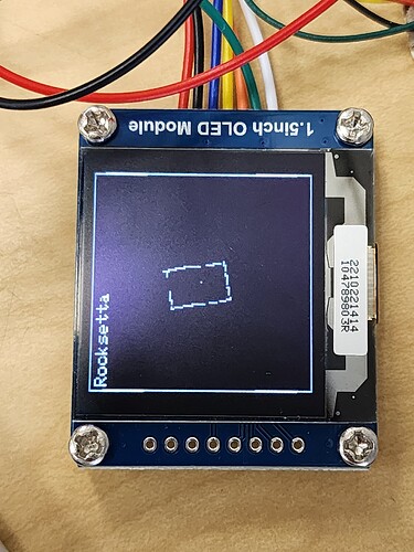
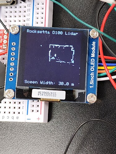
PortentaH7, D100 Lidar by LDRobot and Grayscale OLED

This is my Lidar checksum header routine:

#ifndef LIDAR_CHECKSUM_HEADER
#define LIDAR_CHECKSUM_HEADER

#include <Arduino.h>
#include "LIDAR_LD06.h"

#define POINT_PER_PACK 12
#define HEADER 0x54

typedef struct __attribute__((packed)) {
    uint16_t distance;
    uint8_t intensity;
} LidarPointStructDef;

typedef struct __attribute__((packed)) {
    uint8_t header;
    uint8_t ver_len;
    uint16_t speed;
    uint16_t start_angle;
    LidarPointStructDef point[POINT_PER_PACK];
    uint16_t end_angle;
    uint16_t timestamp;
    uint8_t crc8;
}LiDARFrameTypeDef;

//The CRC check calculation method is as follows:
static const char CrcTable[256] ={
    0x00, 0x4d, 0x9a, 0xd7, 0x79, 0x34, 0xe3,
    0xae, 0xf2, 0xbf, 0x68, 0x25, 0x8b, 0xc6, 0x11, 0x5c, 0xa9, 0xe4, 0x33,
    0x7e, 0xd0, 0x9d, 0x4a, 0x07, 0x5b, 0x16, 0xc1, 0x8c, 0x22, 0x6f, 0xb8,
    0xf5, 0x1f, 0x52, 0x85, 0xc8, 0x66, 0x2b, 0xfc, 0xb1, 0xed, 0xa0, 0x77,
    0x3a, 0x94, 0xd9, 0x0e, 0x43, 0xb6, 0xfb, 0x2c, 0x61, 0xcf, 0x82, 0x55,
    0x18, 0x44, 0x09, 0xde, 0x93, 0x3d, 0x70, 0xa7, 0xea, 0x3e, 0x73, 0xa4,
    0xe9, 0x47, 0x0a, 0xdd, 0x90, 0xcc, 0x81, 0x56, 0x1b, 0xb5, 0xf8, 0x2f,
    0x62, 0x97, 0xda, 0x0d, 0x40, 0xee, 0xa3, 0x74, 0x39, 0x65, 0x28, 0xff,
    0xb2, 0x1c, 0x51, 0x86, 0xcb, 0x21, 0x6c, 0xbb, 0xf6, 0x58, 0x15, 0xc2,
    0x8f, 0xd3, 0x9e, 0x49, 0x04, 0xaa, 0xe7, 0x30, 0x7d, 0x88, 0xc5, 0x12,
    0x5f, 0xf1, 0xbc, 0x6b, 0x26, 0x7a, 0x37, 0xe0, 0xad, 0x03, 0x4e, 0x99,
    0xd4, 0x7c, 0x31, 0xe6, 0xab, 0x05, 0x48, 0x9f, 0xd2, 0x8e, 0xc3, 0x14,
    0x59, 0xf7, 0xba, 0x6d, 0x20, 0xd5, 0x98, 0x4f, 0x02, 0xac, 0xe1, 0x36,
    0x7b, 0x27, 0x6a, 0xbd, 0xf0, 0x5e, 0x13, 0xc4, 0x89, 0x63, 0x2e, 0xf9,
    0xb4, 0x1a, 0x57, 0x80, 0xcd, 0x91, 0xdc, 0x0b, 0x46, 0xe8, 0xa5, 0x72,
    0x3f, 0xca, 0x87, 0x50, 0x1d, 0xb3, 0xfe, 0x29, 0x64, 0x38, 0x75, 0xa2,
    0xef, 0x41, 0x0c, 0xdb, 0x96, 0x42, 0x0f, 0xd8, 0x95, 0x3b, 0x76, 0xa1,
    0xec, 0xb0, 0xfd, 0x2a, 0x67, 0xc9, 0x84, 0x53, 0x1e, 0xeb, 0xa6, 0x71,
    0x3c, 0x92, 0xdf, 0x08, 0x45, 0x19, 0x54, 0x83, 0xce, 0x60, 0x2d, 0xfa,
    0xb7, 0x5d, 0x10, 0xc7, 0x8a, 0x24, 0x69, 0xbe, 0xf3, 0xaf, 0xe2, 0x35,
    0x78, 0xd6, 0x9b, 0x4c, 0x01, 0xf4, 0xb9, 0x6e, 0x23, 0x8d, 0xc0, 0x17,
    0x5a, 0x06, 0x4b, 0x9c, 0xd1, 0x7f, 0x32, 0xe5, 0xa8
};

uint8_t CalCRC8(char *p, uint8_t len){
    char crc = 0;
    uint16_t i;
    for (i = 0; i < len; i++){
      crc = CrcTable[(crc ^ *p++) & 0xff];
    }
    return crc;
}

#endif // LIDAR_CHECKSUM_HEADER
Oh I see. There was an if statement in a loop using (TOTAL_DATA_BYTE - 1). I just must have thought, why not just set TOTAL_DATA_BYTE = 47 so I don't have to subtract 1 :slight_smile:

@jhaytera There has got to bean easy way to serial print a vector.

This works

  for (int i = 0; i < ld06.data_length; i++) {
    if (ld06.angles[i] > -3 && ld06.angles[i] < 3 && ld06.distances[i] < 300)
      Serial.print("Hit!");
  }

but this does not

  Serial.print(ld06.angles[0]);
  Serial.print("; [1]");
  Serial.print(ld06.distances[1]);
  Serial.print(", ");

I guess it is time to learn about c++ vectors.

Weird I can't serial print vectors using the XIAO esp32S3 but they print fine on the OLED. So I guess I just start plotting points on the OLED which is what I wanted anyway.

OMG this is awesome. Thanks so much @jhaytera I was close to giving up. I can even zoom in


My code is here but might be labelled different when I am happy with it

1 Like

That's awesome! You're welcome. That little display is cool.

Yes. It is a fast 16 bit grayscale 128 x 128 $13 USD oled from waveshare and the Portenta camera is Grayscale anyway.

I use it for a lot of Machine Learning stuff with edgeimpulse.com

I made a few improvements. I still want to get it working on the portenta

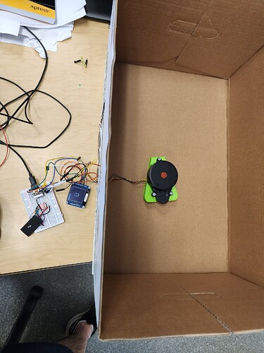
Here it is inside this box

With a screen width of about 1 m it gets great resolution. Objects about 3 inches from the device show up. Any closer and they disappear.

.

With a screen width of 30 m I can scan my entire classroom, which looks reasonably accurate including the top right alcove which has a window. My classroom is about 14 m wide which also looks good. The device is near an open door in the bottom left of the classroom.

I can set the refresh time here at about 8 seconds but a first scan is fairly accurate after about 1 second.

..

As far as the portenta I connected the breakout board with the Lidar to UART 0 (serialUSB) at 115200 baud and getting no readings. When I use Serial1 like with the XIAO I get a few data points then nothing. I think the Portenta needs 9600 baud for Serial1.

2 Likes

I see nothing in the documentation to suggest this and there is no reason why the Lidar unit can not be connected to Serial1 at 115200.

Indeed, in post #18 @jhaytera shows connection at 230400.

Perhaps at some point the Rx pin saw 5v and was damaged. You mention the breakout board, do you have access to the pins for the additional hardware UARTS?

Right, I run my LD06 Lidar at 230400 on the Portenta Breakout Serial1. Declaring Serial1 this way works for me at 230400 baud:

UART SerialLIDAR_UART1(PA_9,  PA_10, NC, NC); // Serial1 on the Breakout Board

void start() {
  SerialLIDAR_UART1.begin(230400, SERIAL_8N1); //--20230113, SERIAL_8N1, pin);
...
1 Like

Thanks for showing the test results! These lidars seem pretty good.

Interesting idea that the UART might be fried. Yes I have access to all the Portenta UARTS

UART myUART0(PA_0,  PI_9,  NC, NC);  // TX, RX, RTS, CTC  NOTE: NC means not connected
UART myUART1(PA_9,  PA_10, NC, NC);   // pin D14 TX, pin D13 RX same as pre-defined Serial1
UART myUART2(PG_14, PG_9,  NC, NC);
UART myUART3(PJ_8,  PJ_9,  NC, NC);
UART myUART6(PC_6,  PC_7, NC, NC);    // pin D5 TX, pin D4 RX
UART myUART8(NC,    PA_8, NC, NC);    // pin D6 RX only can receive

In the above list UART6 and UART8 allow for some interesting non-breakout board UART communication on the portenta. I have some code here for communication between the two cores.

For this situation D6 RX only could possibly be the receive pin for the lidar device.

.

I think I will try a few different Portenta's, since frying them is one of the things I do very well, see Orange LED of Hell.

What the pictures don't show is the time frame to come up with the diagrams. I have my code set for about 8 seconds per refresh, but the main diagram shows up in under a second. I can't wait to put this thing on a toy car and see if it works fast enough to help with the steering.

@jhaytera have you posted your Lidar Portenta code anywhere? I am kind of getting it working. The display freezes after half a second using serial1 when I use a different Portenta. My kind of working code is here

I feel that it will eventually work, I think my code may have a memory leak.

I think I remember my Portenta locking up because I wasn't reading the Serial data fast enough, or some odd thing. Putting the Serail1 read in a loop may have helped. The code I posted above (May 12th for reference) is all from my working Portenta H7 robot project. It's not in one neat program because I have a bunch of other code around. But, those are the routines that handle the lidar data on the H7. Maybe I had to make a change to a variable type in there somewhere... (can't remember what the trick was. Lots of coding!) but that code should work for you. My H7, with my LD06 lidar, runs with that code every day :slight_smile:

We're both incorporating lidar to help machines not crash. Just a matter of time now.

On a side note, check out this sensor:

1 Like

That is a great sensor. I may have to get a few for my class. I think my code is mainly based on your code. Nice that it is now working with the Portenta. The problem I am having might be my OLED, so I am going to go back to basics and see if I can get the Serial monitor showing some data.

Quick question @jhaytera my Lidar can be powered off the Portenta 3.3V and 5V and works from both. I would prefer to use the 5V as I don't like powering motors off 3.3V. Any opinions? Today I was using 3.3V and it was working. I need to test if it actually sends data when powered off 5V.

I have a sperate 5 volts to my lidar and just the TX wire from the lidar to the H7 RX. They share a ground. I think the LD06 outputs 3 volts on the TX line. Working so far. Your lidar may be different.

I'm using one of these to power my Portenta Breakout Board/H7 from a 12 volt lawn tractor battery:

You have to hook it up to a volt meter and turn the tiny screw on the bottom until it reaches 5 volts.

I power other things, like the lidar, at 5 volts from the same 12 volt battery with one of these:

Either one can power both the lidar and the H7. I just wanted a separate supply for the H7.

... and these things make life so much easier :slight_smile: https://www.amazon.com/gp/product/B0BBGPFTK5/ref=ppx_yo_dt_b_search_asin_title?ie=UTF8&psc=1

1 Like

Hola! De casualidad tienes tu código publicado, quiero intentar programar el ld19 en STM 32. Pero antes de eso me gustaría tener una base

Gracias