Position control of DC motor using PID

Hello, I'm trying to control the position of a EMG 30 DC motor using a PID control loop and the feedback given by the optical encoder. What I want to do as a finality is to make the motor oscillate between to positions with a sinusoidal trajectory (that will recquire speed control too I believe). For that I use an Arduino Uno and a motor shield. Unfortunately after having implemented a PID control loop for position that seems correct to me, I'm not able to make the thing work. Actually, my motor starts spinning and then never stops... I use the attachInterrupt function in order to make the motor move in combination with the optical encoder as I have seen it in several other topics on the forum.

I'm very new to Arduino and accordingly I'm not very comfortable with it at the moment. So if anyone has an idea, it would be great. I post my code in order to illustrate my problem. If you need anything else, tell me.

#include "Arduino.h"

int _DIRA = 12;
int _PWMA = 3;
int _BRKA = 9;

#define TRUNCATE(value, mi, ma) min(max(value, mi), ma)

// Maximum error integral
#define SERROR_MAX 32768

// Maximum PWM value
#define PWM_MAX 255

// Gain scaling factor (yes, we want possibly non-integer gains)
#define Kscaling 0.2

// Proportional gain (response speed)
// Ku = 37
#define Kp (37*Kscaling/3)

// Integral gain (speed at which the "drift" is handled)
#define Ki (2*Kp/100)

// Derivative gain (rate of error change handling, probably useless)
#define Kd Kp*10/3

int tick=0;//optical encoder
long Serreur=0;//integral correction
long lerreur=0;//last error
long Derreur;//derivative correction
long sp,dir,cmd,erreur;

void inc() //move forwards
{
  tick++;
}

void dec() //move backwards
{
  tick--;
}

void test(int cmd)
{
  // Compute current error
  erreur = tick - cmd;

  // Error integral, with a maximum value (avoid blowing stuff up in case of drift)
  Serreur = TRUNCATE(Serreur + erreur, -SERROR_MAX, SERROR_MAX);

  // Error derivative
  Derreur = erreur - lerreur;

  // Keep track of the last error value
  lerreur = erreur;

  // Ye olde PID formula
  sp = TRUNCATE((Kp*erreur + Ki*Serreur + Kd*Derreur)/Kscaling, -255, 255);
  
  // Handle speed sign
  if (sp>=0){
    dir = HIGH;
  } else {
    dir = LOW;
    sp = -sp;
  }
}

void encoder() //choose direction to move according to what says the optical encoder
{
  if (digitalRead(2)==digitalRead(4)) //2 and 4 are the pins where the optical encoder is plugged in
  {
    inc();
  }
  else
  {
    dec();
  }
}

// Output the PWM command and direction
void action()
{
  analogWrite(_PWMA, sp);
  digitalWrite(_DIRA, dir);
}

void setup()
{
  pinMode(_DIRA,OUTPUT);
  pinMode(_BRKA,OUTPUT);
  pinMode(2,INPUT);
  pinMode(4,INPUT);
  digitalWrite(2,HIGH);
  digitalWrite(4,HIGH);
  digitalWrite(_BRKA, LOW);
  attachInterrupt(0,encoder,CHANGE);
}

void loop()
{
  cmd=5;
  test(cmd);
  action();
}
Try adding something like delay(5) in loop() so its not racing away at silly speeds - a regular fixed update rate
is essential for the integral and derivitive calculations to be meaningful.

The encoder handling code is not safe so may not work reliably. I suggest you ignore anything to do with motors and PIDs and just get the encoder reading to work reliably before you try anything else. In my opinion, the best way to know that it's working correctly is to print the current value over the serial port at regular intervals and confirm that it updates promptly and accurately, and that there is no slippage between the tick value and the physical encoder position.

Since the 'tick' variable is used in an interrupt context as well as the main context, it needs to be declared volatile. Since it is bigger than a byte, you need to suspend interrupts around accesses to it in the main context to prevent it from changing while you're accessing it. The best approach is to suspend interrupts, copy the volatile variable to a local variable and re-enable interrupts, so that interrupts are disabled for the shortest time possible.

I did what you said about the optical encoder ; I know now the exact number of transitions of the encoder pin on one round of the motor.

I think my function Encoder which is to have the information of where we are on the optical encoder wasn't good. As it is a quadrature encoder, I've rewritten the function : attachInterrupt is triggered on a rising edge of the first pin of the encoder (plugged in pin 2) and the counter tick is increased if the second pin is LOW and decreased if it's HIGH. So that must be more correct.

I also changed the calculation of integral and derivative errors which is now made regularly.

But my new code doesn't seem to work... I didn't get what you mean with the volatile thing for a variable which appears in a function used by attachInterrupt.

Sorry if I seem a little confused, it's just that it is the first time I'm using arduino or doing non-theoretical electronics and I'm totally on my own so I'm not very comfortable...

There's my new code to see what I've corrected

#include "Arduino.h"

int _DIRA = 12;
int _PWMA = 3;
int _BRKA = 9;

float Kp,Ki,Kd;

#define TRUNCATE(value, mi, ma) min(max(value, mi), ma)

// Maximum error integral
#define SERROR_MAX 32768

// Maximum PWM value
#define PWM_MAX 255

// Gain scaling factor (yes, we want possibly non-integer gains)
//#define Kscaling 0.2

// Proportional gain (response speed)
// Ku = 37
//#define Kp (37*Kscaling/3)

// Integral gain (speed at which the "drift" is handled)
//#define Ki (2*Kp/100)

// Derivative gain (rate of error change handling, probably useless)
//#define Kd Kp*10/3

int tick;
long i_error;
long lerreur;
long d_error;
long sp,dir,cmd,erreur,pos,time1,timecur,dt;


void inc()
{
  tick++;
}

void dec()
{
  tick--;
}

void test(int cmd)
{
  timecur=millis();
  dt=timecur-time1;
  time1=timecur;

  // Compute current error
  erreur = tick - cmd;
  i_error = i_error + erreur * dt;
  d_error = (erreur - lerreur) / dt;

  // Error integral, with a maximum value (avoid blowing stuff up in case of drift)
  

  // Keep track of the last error value
  lerreur = erreur;

  // Ye olde PID formula
  sp = Kp*erreur + Ki*i_error + Kd*d_error;
  sp=constrain(sp,-255,255);
  
  // Handle speed sign
  if (sp>=0){
    dir = HIGH;
  } else {
    dir = LOW;
    sp = -sp;
  }
}

void encoder()
{
  if (digitalRead(4)==LOW) //2 and 4 are the pins where the optical encoder is plugged in
  {
    inc();
  }
  else if (digitalRead(4)==HIGH)
  {
    dec();
  }
}

// Output the PWM command and direction
void action()
{
  analogWrite(_PWMA, sp);
  digitalWrite(_DIRA, dir);
}

void setup()
{
  tick=0;
  i_error=0;
  d_error=0;
  Kp=0.5;
  Ki=0;
  Kd=0;
  pinMode(_DIRA,OUTPUT);
  pinMode(_BRKA,OUTPUT);
  pinMode(2,INPUT);
  pinMode(4,INPUT);
  digitalWrite(2,HIGH);
  digitalWrite(4,HIGH);
  attachInterrupt(0,encoder,RISING);
  time1=millis();
}

void loop()
{
  //360 ticks par tour de l'arbre moteur
  //Rapport de réduction 30
  pos=60; //Position de l'aile à atteindre en °
  cmd=pos*90/360; //Position à atteindre pour l'arbre
  test(cmd);
  action();
  delay(5);
}

First of all, if you're trying to control position for a DC motor, prepare for big headaches :grin:!. Now, this is an efficiente code to track position, it will give you double or quadruple encoder resolution:

volatile long enc_count = 0;

void setup(){

Serial.begin(9600);

attachInterrupt(0,encoder_isr,CHANGE);
attachInterrupt(1,encoder_isr,CHANGE);

}

void loop(){

noInterrupts () ;
int Position = enc_count; //read the variable atomically, interrupts deferred
interrupts();
Serial.println(enc_count);

}

// 4X encoder resolution
// Channels A|B: Pin: 2|3
//void encoder_isr() {
// static int8_t lookup_table[] = {0,-1,1,0,1,0,0,-1,-1,0,0,1,0,1,-1,0};
// static uint8_t enc_val = 0;
//
// enc_val = enc_val << 2;
// enc_val = enc_val | ((PIND & 0b1100) >> 2);
//
// enc_count = enc_count + lookup_table[enc_val & 0b1111];
//}

// 2X encoder resolution
// Channels A|B: Pin: 3|4
void encoder_isr() {
static int8_t lookup_table[] = {0,0,0,-1,0,0,1,0,0,1,0,0,-1,0,0,0};
static uint8_t enc_val = 0;

enc_val = enc_val << 2;
enc_val = enc_val | ((PIND & 0b11000) >> 3);

enc_count = enc_count + lookup_table[enc_val & 0b1111];
}

As PeterH suggested, the interrupt is suspended and its value is assigned to the position variable.

Gilgamesh90:
First of all, if you're trying to control position for a DC motor, prepare for big headaches

Not really, in essence its just a PID loop, though just PI will work. As always you have to
tune the coefficients for non-oscillatory and prompt response.

position_error ----> PID loop ----> motor drive level and direction.

MarkT:

Gilgamesh90:
First of all, if you're trying to control position for a DC motor, prepare for big headaches

Not really, in essence its just a PID loop, though just PI will work. As always you have to
tune the coefficients for non-oscillatory and prompt response.

position_error ----> PID loop ----> motor drive level and direction.

PID is the easy part, unfortunately there are other factors like, maping the PID to PWM, motor inertia, etc. that make position control a hard job.

Hi, what frequency of oscillation are you aiming to get the shaft to go forward/reverse.

Tom......... :slight_smile:

Herr_Spaetzle:
I didn't get what you mean with the volatile thing for a variable which appears in a function used by attachInterrupt.

Variables which are used in the main context code and also used in interrupt context code need to be declared volatile. If you fail to do that, the compiler may wrongly optimise accesses to that data causing data corruption. In your case, the variable tick needs to be declared volatile. Search for "C++ volatile" if you want a more detailed explanation.

You also haven't disabled interrupts around access to tick in the main context.

@Gilgamesh90
Could you explain a little bit your code for tracking position, I'm a little bit confused... I've tried to use it just with a simple rotation of the motor but it prints only 0, I might not use it in a good way...

@TomGeorge
Not a frequency in particular, I need to be able to chose a frequency in the range [0.5Hz, 5Hz].

Actually, I tried your code Gilgamesh90 with plugging the optical encoder on pins 2 and 3 or on pins 3 and 4 and the motor on pin 11, but it doesn't count anything and stays at 0 although the motor is spinning.

I've already spent much time on this programm and it seems I can't get the optical encoder to work. The PID part isn't a problem for me, but everything I tried to read the encoder doesn't seem to work. If someone could give me a large amount of help for this it would be great.

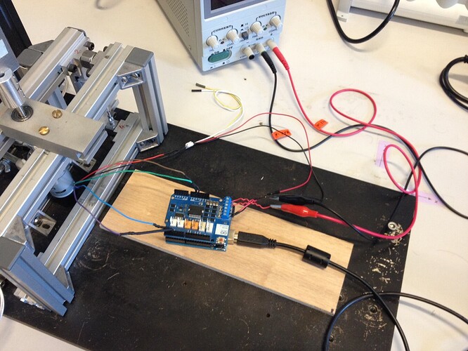
OK. I just tried the code again and it works. Now, what arduino are you using? I'm using Arduino UNO R3. In order to make sure the sketch is working, dont turn on the motor, just connect the encodder channels and then turn the shaft manually. You should see the number increasing or decreasing (depending of the rotation direction). It would be great if you could show us some schematics or photo of your setup! (Don't forget to connect Vcc and ground for the encoder: green and brown cables.)

I'm using an ARDUINO UNO R3 too. I can describe my setup if you want :

  • an ARDUINO Motor Shield is on my UNO
  • encoder is linked to 5V and GND pins with green and brown wires and to pins 2 and 3 for the 2 other wires (blue and violet if the colors meant to be standard)
  • the motor itself (red and black wires) is connected to the +/- pins of the motor shield on the B-side
  • the motor shield is linked to a regulated generator delivering from 0 to 12V

I will send a picture of the setup as soon as I can.

Okay, here is my setup (here the encoder is plugged on pins 2 and 3 (blue and purple wires) but I've also tried pins 3 and 4).

I've tried to turn the motor only with my hand but the counter still stays at 0. Nothing happens. Although the setup seems fine to me... I don't see what could be the problem at this point. The optical encoder works properly I think because I managed to count something with serial monitoring with another code (I don't know if it counts well (I think it does) but at least it counts...)

Try the code without the shield. I tested the code without any shield.

Okay, I've tried without the motor shield, just the Arduino, optical encoder plugged on 5V and GND (brown and green) pins and on digital pins for blue and purple wires (I've tried pins 2 and 3 and pins 3 and 4), and the Arduino linked on my computer via the USB, but the counter still stays stuck at 0.

Hi, have you tried googling? arduino rotary encoder

http://playground.arduino.cc/Main/RotaryEncoders

Just try that example on its own.
Also can you tell us the make/model of the motor and make model of the encoder, some encoders need a pull up resistor on their outputs.
Have you actually measured changing levels out of A and B outputs?
Also if you are trying to get it to oscillate over say 1/2 or 1 turn then your encoder may not have the resolution.

Tom...... :slight_smile:

I managed to have a functionning code for counting the encoder, only with the double resolution but it's enough at the moment. I've also tuned my PID controller almost as I want. The last problem I might have is to give a command to my motor so the movement of the motor is sinusoidal as function of the time. I've tried something like :

timecur=millis();
command=60*sin(0.5*timecur);

But that doesn't work, nothing moves...
If anybody has an idea to do this... I keep looking on my side.

@TomGeorge I've read a lot of things on rotary encoders before posting, but now it's solved. My motor is an EMG30. Here's the datasheet EMG30 data.