My potentiometer seems to be faulty or im doing sometthing very wrong
int const potPin = A0;
int potVal;
int angle;

void setup() {
  // put your setup code here, to run once:
  Serial.begin(9600);
}

void loop() {
  // put your main code here, to run repeatedly:
  potVal = analogRead(potPin);
  Serial.print("potVal: ");
  Serial.print(potVal);

  angle = map(potVal, 0, 1023, 0, 179);

  Serial.print(", angle: ");
  Serial.println(angle);

  delay(15);
}
Im not sure if its a problem in the code or my circuit:
If you are serious in needing help, begin by supplying at least a block diagram showing your circuit, including power supply. Pictures are a waste of both our times in the beginning of a thread. Suppose I sent you a picture of the solution and nothing else.
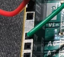
Nice picture not very informative but from what I can see the pot is on 3V3 and 5V. You want it on 5V and ground assuming it is at least 1K.
Your readings indicate an open analog wire or a bad port on the Arduino. Try one of the other pins.
Place a jumper from ground to A0, you should get consistent low value readings. Then to the 3Ve and 5V the numbers will be different but they should be stable. If so it is a bad connection or pot.
You should have a resistor in series between the pot centre-tap and the analog input pin, and a small capacitor to ground (0v). This is so you are not connecting +5v or ground directly to the analog input pin, and the cap will filter noise if the pot is not quite perfect.
The series resistor and cap also allow the chips internal overvoltage/ESD protection a chance to work.
The resistor can be anything from 1k upwards to even 100k, 10k is probably safest, and the cap can be anything from 100nF to 100uF depending on how fast you expect the signal to be changing.
Those breadboard connections with the jumper wires are notoriously unreliable - you might find if you disturb the wires the values change too.
EDIT: in fact the cap C1 could be the other side of the resister, but I dont think it will make much difference in this case.
If the analog signal was coming from some unregulated/uncontrolled far away source (instead of the arduiunos own +5v), then you would have to do much more for protection of the analog input.
i added the capacitor to the ground and added a resistor between the pot and then analog pin. its now basically just stuck on the value 178/179 and twisting it does basically nothing
Well I guess it's not a problem when it's the Arduinos own +5v, I was thinking of protecting the input pin if the wires and pot (or some other device) become more remote or powered from a different source. So many of those really basic examples dont teach anyone about taking that tiny example to the real world where there is contact bounce and all sorts of other electrical noise.
The problem is that in trying to write an example of one thing, such as reading a switch input(), if you include contact contact bounce elimination the code rapidly becomes so complicated to someone who just wants to read a switch state that the basic functioning of the code is swamped. Add in the need for pullup or pulldown resistors and the description of how to wire them or use INPUT_PULLUP and the originator of the question is likely to run a mile
It is instructive to write a tutorial on a subject. Many Moons ago I wrote a tutorial on the use of millis() for timing and felt the need to say this as a start
In the sample programs below there are some assumptions made as follows :
You know how to set the pinMode() of an input and output
Pins A1, A2 and A3 are used as digital inputs but any pin other than 0 and 1 can be used.
Input pins are defined as INPUT_PULLUP in pinMode() and that closing the associated switch takes the pin LOW
Pins 10, 11, 12 and 13 each have LEDs attached via a current limiting resistor to 5V, so taking the pin LOW turns on the LED
Pins 10 and 11 are capable of PWM output when required.
Variables used will be declared as globals for ease of use but purists may want to declare some of them locally
The programs in this thread have been written and tested on a Uno but will run on most/all Arduino boards
If I had not listed the assumptions then I could not have introduced the example sketches without a great deal of preamble. As it was I received comments that the start of the tutorial was too wordy and that it should have jumped straight in with example sketches, but I hope that the 450K or so views that the tutorial have had have proven useful to some users