Connection :
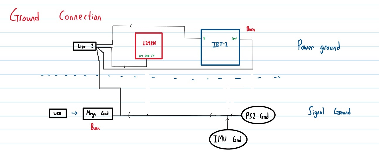
I would like to use an Arduino to control two motor. The two motor driver I used is L298N which supports up to 2A and IBT-2 which supports up to 43A . The IBT-2 is connected to a motor which rated as 5.5A. To power both of the motor driver together, I connect two 3s(11.1V), 5400mAh Lipo battery in series which produce 22.2V in total and regulate the voltage on 12V by using a buck converter. I also have PS2 controller and one more sensor which is called (IMU) connected to the Arduino as an input.
Problem :
For L298N, we have to connect the ground of power source and signal source (Arduino's Ground) together to common ground them. This circuit actually works at first but burns after a few test run. There are smokes coming out but not sure where is the source. Visibly we cant see anything burned but our Arduino Mega and IBT-2 spoils after testing.
Suspect :
What we suspect is the power ground current flows into the signal ground instead of back to Lipo battery.
Question :
I would like to know what I did wrong? If the problem is not like what I suspect, then what will be the real problem here? Last, how to prevent this kind of problems happen again?
Hi,
You need to "star" connect your gnds at the Lipo, so each motor module motor current flows in its own ground wire.
That way no motor current flows in the signal ground wire.
This will also protect your Mega against heavy shorting/starting currents from your motors.
What gauge wire are you using?
Can you please post some pictures of your project so we can see your component layout?
You appear to have routed the return current from the IBT2 on a wire between IMU and Mega,
unless that wire was nice and thick (10mm^2 or so) and secured soldered at both ends, that's
probably where the destructive voltage appeared to fry things, either due to the wire resistance
or connector resistances (connectors can have significant resistance, note).
Never share ground or supply current between high current loads and logic circuitry.
I have redrawn the schematic for clearer view. Sorry that I cannot show the pictures of my project as I don't have access to the workshop anymore due to covid. What I want to clarify here is that the GND at the IBT-2 is the signal ground while the B- is the power ground.
Gil:
I did not draw the connection between the Ground and the B- but the connection is actually connected internally.
Tom:
I have read through some of the concepts of star grounding. But I find it hard to apply and figure out the connection. Based out the figure you drew, Arduino's ground will be shorted to LiPo's ground? Can you elaborate more?
Hi,
In your circuit you have the Arduino gnd connected to the Lipo ground, but the Arduino ground current is SHARING the motor current path.
This means that any heavy motor current in the shared path will cause a changing voltage drop along that path, this will mean the ground of the Arduino will not be at ground but some voltage drop across the path above it, this can cause the Mega to reset or digitally glitch, upsetting your code.
The ground is not a perfect conductor, it has resistance, no matter how small.
By moving the Arduino ground to where I have shown on your circuit, the motor current does not share the Arduino ground circuit even though they are still connected to the same point.
This is star grounding for an Arduino and sensors/controllers:
[ the signal wiring and motor wiring is omitted for clarity ]
Note that the high current wiring (drawn thicker) is nowhere near anything else
and certainly is never shared with sensors or logic circuitry.
Also the wiring to sensors is kept separate from sources of noise like drivers.
Also note that the ground wire (not B-) between the two motor drivers may also
carry high currents, since it is effectively in parallel with the B- wiring, but that
the current is only that of the L298, the lower current driver - the fact that I've
drawn the IBT-2 closer to the LiPo supply is not an accident.
The shared path between Arduino's ground current and motor's current is identified by A. Did I identify it correctly? (See the picture attached, the path A is highlighted with light blue)
I am not sure how the Arduino's ground voltage will be at voltage drop across the shared path. I cannot figure it out because I am not sure which node to make it reference voltage.
Arduino is powered by USB power bank so far. Will that complicate stuff if I connect's Arduino's ground straight to LiPo's Ground?
MarkT:
Sorry, but did you include the circuit drawing? The ground wire at the last paragraph you mentioned is signal's ground connected to Arduino?
Once again, sorry for late replies and I am really thankful for you guys' guidance cuz I have burned quite some money due to this.
Alright, I think this discussion can only progress with pictures of actual wiring and the gauge of the wires used. But that will take me around 1 month only then I can enter the campus. Is it ok to let this post stagnant for 1 month and revive it or should i closed this post and open a new one with actual wiring?
Thanks a lot for all of your inputs, especially the star grounding connection.
cheesecake22:
Is it ok to let this post stagnant for 1 month and revive it or should i closed this post and open a new one with actual wiring?
I suggest you leave it as it is. You can't 'close' it, whatever you think that means. After 120 days it will be locked automatically. If you continue here then everyone who wants to contribute will be able to see the full story, just don't leave it too long.