I have an RGB LED (common cathode) that I am driving off of analog pins A0, A1, and A2 on the Arduino Nano RP2040 Connect.
I recently decided that I wanted to try to use one of the LEDs (Green) as an initial "power on" LED that will get illuminated as soon as power is applied to the board but that can then be turned off/overridden in software once the board has entered into setup().
Initially I was going to do this by effectively via a logical NOT gate using a transistor and using one of the digital out pins to control it -- when the power is first applied, the digital out would be low, and the "gate" would output a high signal, driving the LED. Then in setup() I would set the digital output to high and that would switch the gate to low and allow the analog out pin (A1) to drive the LED. I was going to add a diode in there to make sure current only flowed one direction if needed.
However, in prototyping this, I discovered that everything worked as needed simply having a high-value resistor from Vcc to the lead to the green LED. This would supply enough current to the LED to illuminate it and once the PWM of the analog out pin took over, did not seem to effect the color of the LED when driven from the software.
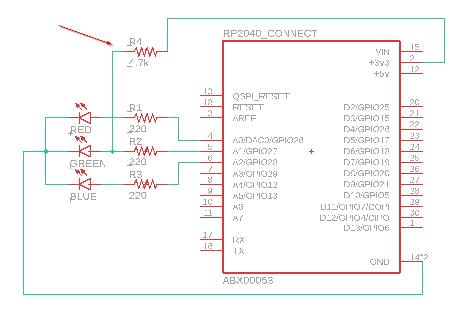
The schematic of the final setup is below.
My question to the forum is ... is what I am doing "bad" in any way? Will it damage the Arduino?
I'm not 100% sure what is going on under the hood -- my expectation was that the connection through the high value resistor would contribute a certain amount of current to the LED so the green LED would always be slightly on. But what appears to be happening is that when the LED is being driven by the analog pin, and -- I assume -- when the PWM cycle is "off" it is actually drawing current back into the analog pin (i.e. the A1 pin is acting as a ground during the off part of the PWM cycle). I also assume that during the "on" phase of the PWM, the current from the analog pin is dominating the LED and the amount of current contributed through the high value resistor is negligent, so not "adding" a significant amount of current to the green LED.
If my assumption is correct... is this temporary "reversal" of current flowing back into the analog pin during the off part of the PWM cycle a bad thing? Will I damage the board in any way by having this happen?
Thanks!
---Lawrence