since typical powerbanks I had (which are working) didn't have the right shape for my arduino project, I bought a specific one.
Unlike the other ones, it has only USB C outputs.
If I connect the arduino to it, no power at all is provided!
It is NOT the phenomena that a powerbank shuts off because of too little power draw after a couple seconds (that should not be an issue here since over 300 mAh are drawn once the arduino nano has activated multiple mosfets).
The LED of the arduino does not even flicker.
The powerbank has 2 USB C outputs. A smartphone attached to the other is charging but yet no power on the one with the uC. Of course I've swapped the ports with no change.
Does this powerbank somehow require communication with the consumer to draw power?
Can I fake that somehow in a safe manner?
It was hard to find a powerbank of the right shape and since this is for inside a costume, I do not want to assemble a Li-Ion power supply myself and yet would like the power density.
Huge thanks in advance
P.s. I can provide a link to the powerbank if that helps somehow but think it's really generic, just rather compact, and don't wanna have my first post here look like an ad.
If the powerbank is a 5.1V type but you are plugging it into a 5V jack on an arduino, the volatge regulator will need roughly 6.5V. If you instead use the arduino USB port it should work.
Am testing/using an Arduino Nano with built in USB-C connector and am connecting to it with a 4-wire cable that allows me to also reprogram it (if plugged into the PC instead of the powerbank.
Alternatively in the final construction (same powerbank behavior) I'm using a tiny prebuilt board with a female USB-C connector and forwarding to a male USB-C for the Nano so that I can have a reliable connection for the 5V. I didn't wanna use the 5V and ground pins of the Arduino to draw the 300mAh power since that was rather close to the limit according to somebody here.
That sounds very promising! Interesting that that's a thing. Guess that's the price we pay for the fact that USB-C can be plugged in both ways?
Hmm, how would one do that? Do I have to solder those incredibly tiny pins of an USB-C connector? Or does the Nano happen to do something with those pins as well?
The board I mentioned only provides power and the two D-lines as solder points.
Almost impossible to solder the wires, best is to make a small board with a female USB-C breakout on one side and a male USB-C breakout on the other. It will be a lot easier to solder those pins.
I think we have to establish exactly what the Nano is. Then we can look at its schematic. But I would say if it's a real Arduino with a USB connector, it certainly would have the CC resistors already. And I would think even a dodgy clone would have them too.
Actually, if the CC resistors are present on the Nano, you should be able to find them with your multimeter. They are 5.1K.
I see that regular Nano clones are being sold on AliExpress with the option of micro, mini, or USBC connectors. But all three are pictured with cables having a USB-A plug on one end. If the manufacturers are assuming such a cable would be used, then the CC resistors would not be needed since that's just regular 4-wire USB 2.x. So I guess it's possible they would not have the CC resistors. But again, it should be easy to find out if there are two 5.1K resistors on the Nano.
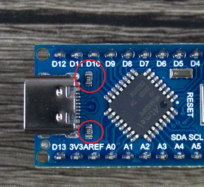
Edit: Here's a picture of one such Nano with the CC resistors plainly marked "512", which is 5.1K. In similar Nanos they might be on the bottom of the board near the connector.
I just tried a genuine Arduino Uno Mini with USB-C and a USB-A to USB-C cable and it powered and programmed like you would expect using the Arduino IDE.
It also powers and runs the sketch when powered through the USB-A connector on a power bank. When plugged into USB-C on a power bank with only USB-C connectors through a standard USB-C cable it also works perfectly.
Conclusion: Try a USB-C cable with all the wires not just Voltage and data.
It is the classic, not the ESP32. Judging by the price since it was not from China directly, I thought it was an official USB-C version now. Should've researched more, I suppose.
@ShermanP
There are two like that on the backside near the USB-C.
Yeah that's it indeed. Thank you for the hint!
When connecting a proper USB-C cable to the Nano directly, it works. Guess I always had my contraption inbetween which only forwards the 4 wires.
Have ordered USB-C break-out boards with all pins now.