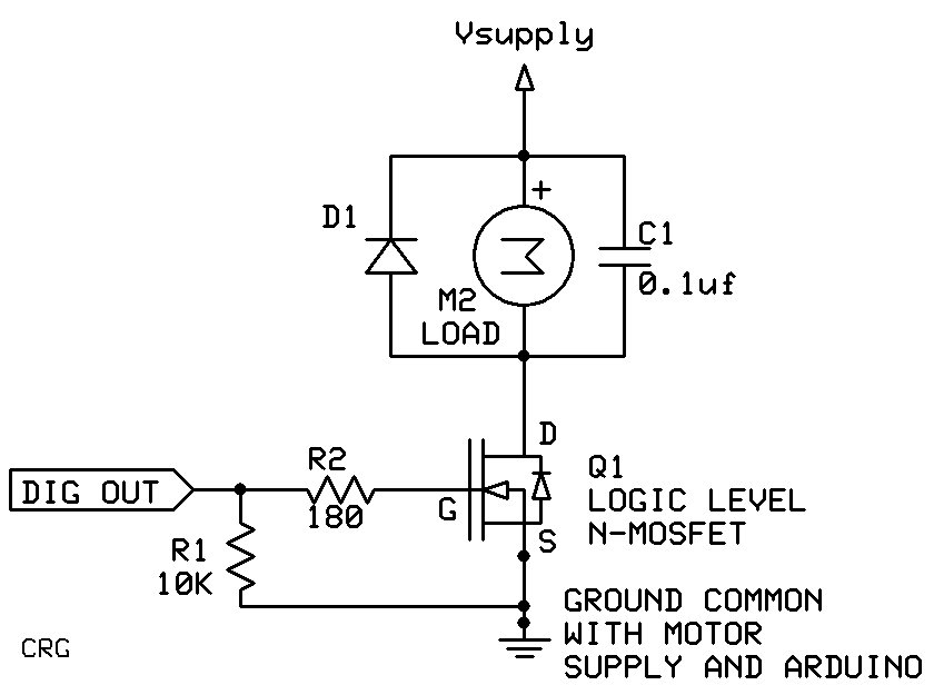
I'm constructing a compact bluetooth-activated 12v pump using an Arduino Uno. I only want to have one power cable going into the unit, so I want to use the same 12V power supply for both the power input into the Arduino, and for the pump itself. I'm using the PN2222 transistor to use a digital signal from arduino to switch the pump on and off.
I've attached a schematic of my circuit, apologies for its poor quality.
I'd like to get the following input:
Is this a sensible/feasible approach? I originally used a relay but it seems like a transistor is more appropriate as a relay requires a 5V power supply
What resistors should I add to the circuit? I guess I should put one between pin 9 and the transistor? What resistance should it be?
Is it okay to split the 12V power into two lines like I have done?
What resistors should I add to the circuit? I guess I should put one between pin 9 and the transistor? What resistance should it be?
Yes, how much current does the pump draw? You also need a kickback diode in parallel with the pump,
1N4004 will work, cathode (end with band) toward +V.
The spec that you need to know to choose a brushed DC motor driver and power supply is the stall (starting) current. You can estimate the stall current by measuring the motor coil resistance (resistance across the motor power wires) and dividing the motor supply voltage by the measured resistance. Measure the resistance, turn the motor a bit, stop, measure, turn, stop, measure, ... Do that a few times and take the lowest resistance for the calculation.
A 2N2222 is good for 600mA, maximum. Is that more than the calculated stall current? If not you need to choose a better motor driver (ie. a MOSFET).
Do not power the Arduino through the Vin or the power jack. Powering through Vin or the power jack means that the Arduino and all peripherals that are on the 5V rail are powered by the onboard 5V regulator. The on board 5V regulator is not heat sinked so will supply limited current before it overheats and shuts down. The recommend max power dissipation for the regulator is 1 Watt. With 12V into the regulator the max current is about 140 mA (1W / (12V - 5V)). The Arduino uses around 50ma of that leaving less than 90mA (max) for everything else. I would use a buck converter to drop the 12V to 5V and connect that to the 5V on the Arduino, bypassing the, weak, 5V regulator. The buck converter also will provide isolation from the motor electrical noise.
groundFungus:
The spec that you need to know to choose a brushed DC motor driver and power supply is the stall (starting) current. You can estimate the stall current by measuring the motor coil resistance (resistance across the motor power wires) and dividing the motor supply voltage by the measured resistance. Measure the resistance, turn the motor a bit, measure, turn, ... Do that a few times and take the lowest resistance for the calculation.
A 2N2222 is good for 600mA, maximum. Is that more than the calculated stall current? If not you need to choose a better motor driver (ie. a MOSFET).
Okay, I shall do this and switch to a MOSFET, is there any particular one you recommend?
groundFungus:
Do not power the Arduino through the Vin or the power jack. Powering through Vin or the power jack means that the Arduino and all peripherals that are on the 5V rail are powered by the onboard 5V regulator. The on board 5V regulator is not heat sinked so will supply limited current before it overheats and shuts down. The recommend max power dissipation for the regulator is 1 Watt. With 12V into the regulator the max current is about 140 mA (1W / (12V - 5V)). The Arduino uses around 50ma of that leaving less than 90mA (max) for everything else. I would use a buck converter to drop the 12V to 5V and connect that to the 5V on the Arduino, bypassing the, weak, 5V regulator. The buck converter also will provide isolation from the motor electrical noise.
Hmm okay, and you don't reckon that will be enough for the bluetooth module and one digital output pin to be used? Using a buck converter will increase the footprint of the unit somewhat and also increase the amount of soldering I'll to do (I'll have to make lots of these units).
a MOSFET, is there any particular one you recommend?
What is the pump motor stall current? Through hole or surface mount?
Why have you added a capacitor to the motor part of the circuit?
The cap will help to filter out motor electrical noise.
To use the buck converter is up to you. If your testing shows that the project will work reliably while powered by the 12V motor power to the onboard regulator and the regulator does not get too hot, then it is not needed. But if the regulator gets hot and/or you need more isolation from motor noise, then it the converter would be called for.
groundFungus:
A 2N2222 is good for 600mA, maximum. Is that more than the calculated stall current? If not you need to choose a better motor driver (ie. a MOSFET).
Okay, i turned the motor by hand and measured the resistance each time. The range was 14.1 - 14.4 Ohms. It's a 12V motor so 12/14.1 = 0.85, so this means the current stall will be 85 mA, and the PN2222 (rated up to 600mA), should be adequate?
and the PN2222 (rated up to 600mA), should be adequate?
No.
The pump draws 46mA of current when on.
The running current is not as relevant as the stall current when choosing a motor driver. A motor driver needs to be able to comfortably handle the starting (stall) current. I recommend using a logic level MOSFET that good for around 1A and a low Rds(on).
groundFungus:
The running current is not as relevant as the stall current when choosing a motor driver. A motor driver needs to be able to comfortably handle the starting (stall) current. I recommend using a logic level MOSFET that good for around 1A and a low Rds(on).
Thanks for all your help. So this N-MOSFET, with a Maximum Continuous Drain Current of 1A and a Maximum Drain Source Resistance of 750 mΩ would be suitable?
I would look for a MOSFET with a lower Rds(on). 750mOhms is kind of high. And the power dissipation would be more than that MOSFET is rated for (I2R = P = 0.85A0.85A*0.75Ω = 0.54W, max for the MOSFET 0.3W)
A quick look at RS I find the FDN337N 2.2A 0.065mOhm. The higher current rating will not hurt.
Ha okay the FDN337N arrived but that thing is way too small for my rubbish soldering skills. Could you recommend a through-hole alternative? The FDP8880 is the closest I could find, but it has a much higher Maximum Continuous Drain Current of 11A.