thanks for the details mark,
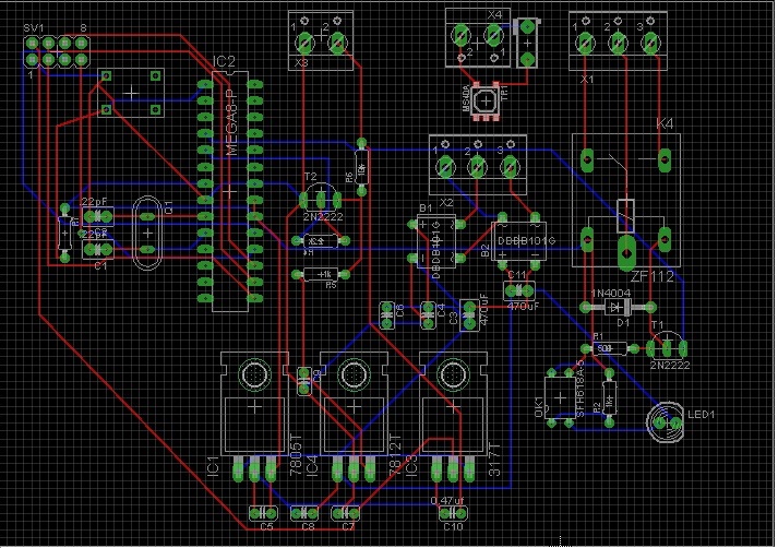
You cannot run two full-wave rectifiers from the same secondary winding like that - they each need a separate winding.
oh i see. so i would need 2 different transformers ?
You don't have enough separation on the board between high voltage and low voltage parts - minimum of 10mm would
be a good starting point. (I'm assuming the relay contacts are high voltage).
alright, i will look into that.
Also I see no 0.1uF decoupling capacitors on the ATmega,
i haven't needed to use them on a bread board circuit. so never thought to use it. where are you suggesting the use of the decoupling capacitors ?
and is there a ground plane for the logic area of the board?
sorry, i dont quite understand what that means.
Supply traces should to be thicker than signal traces, and the traces running to a fuse need to be able to carry more
current than the fuse!
yeah i realize that, but what size would you suggest per amp ? so i can have a better idea.
Also AREF should not be connected to AVCC, it should just have a ~ 0.1uF capacitor to ground on it.
alright , will make the changes.
All the supply connections to the chip should meet underneath it, not run round the edges of the board, (ditto ground)
hmm, alright, ill make those changes as well.
both supply pins take 0.1uF ceramic decoupling caps right next to the relevant pin.
you are talking about the caps across the regulators right ?