Powering the Nano RP2040 Connect through a 5V regulator

Hi all,

I started a little project for fun, the aim is to interact with my apartment's intercom system to receive phone notifications when someone rings the bell and to open the building door remotely.

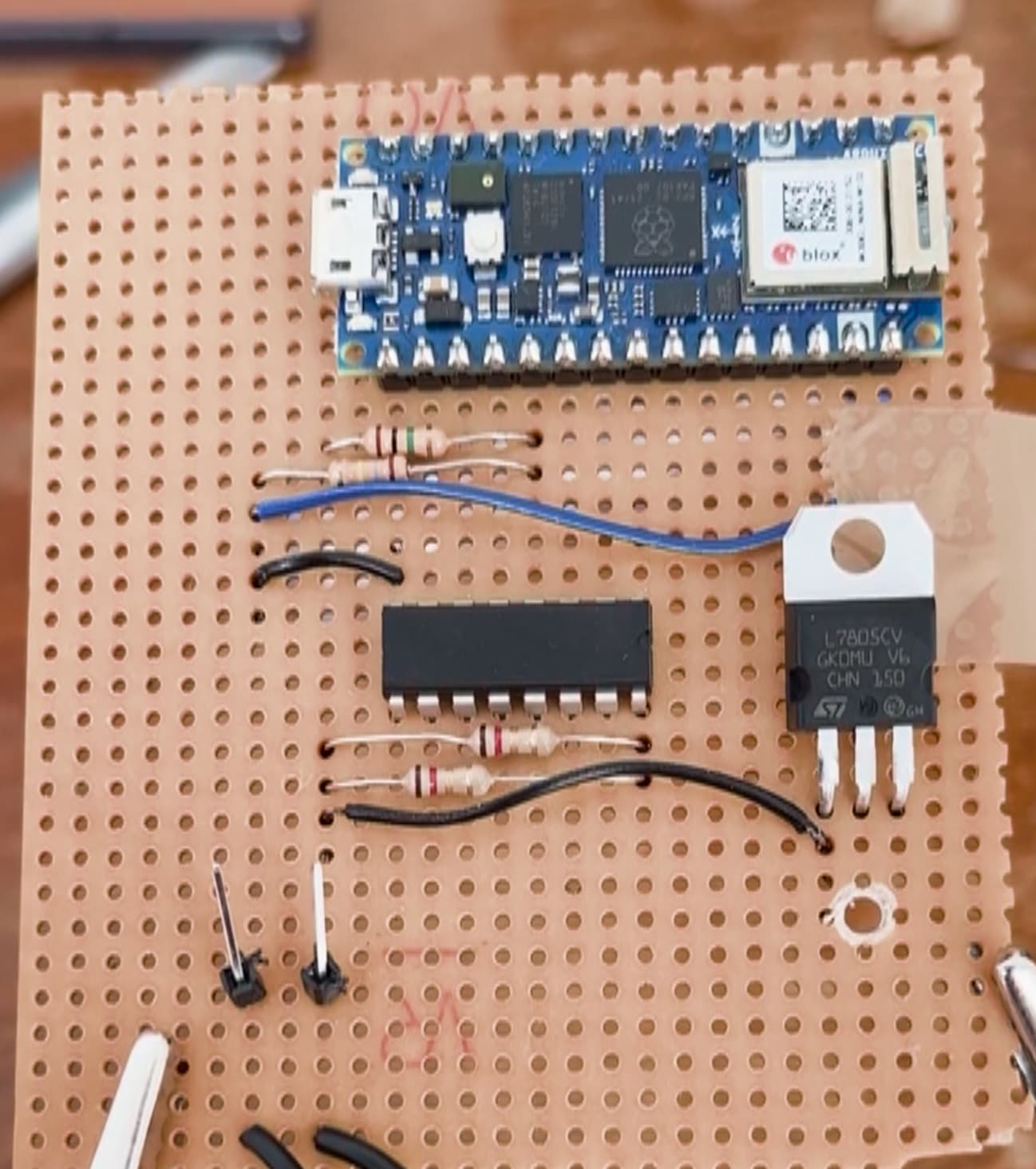
I followed in the footsteps of someone else, and thought I would make a small modification to power the circuit from the intercom directly, so I can hide the whole thing in the unit next to the door.

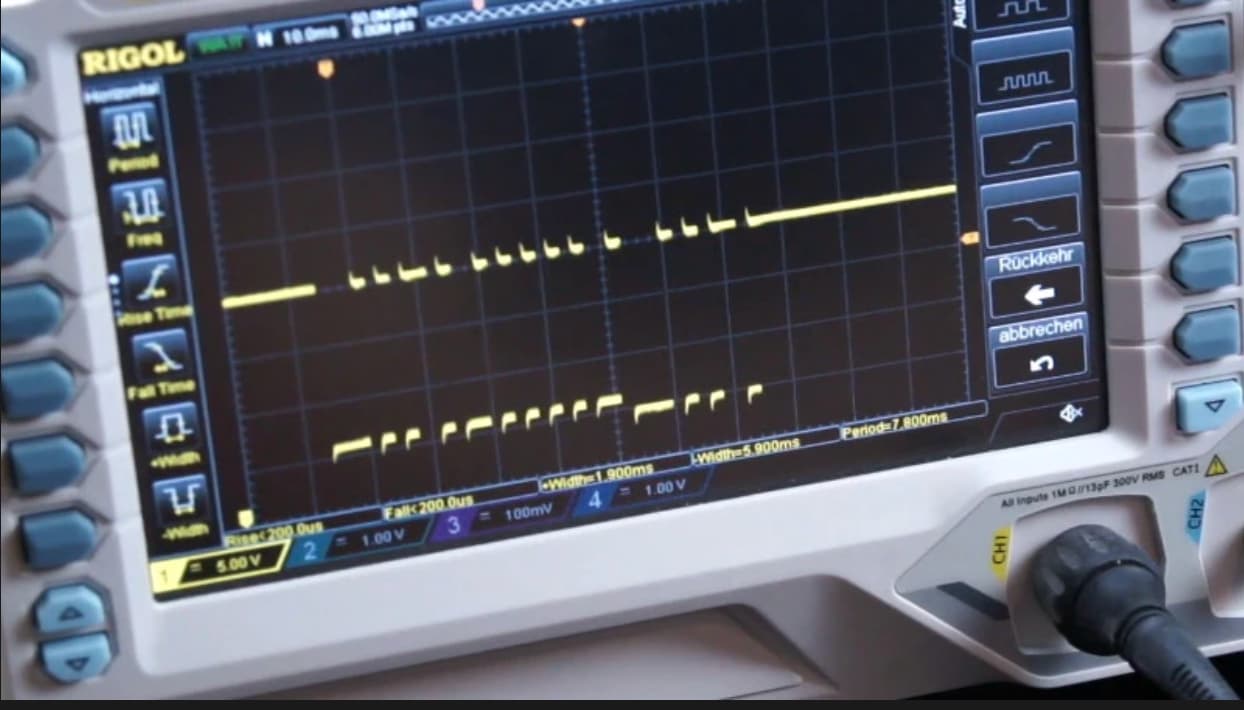
I got the first part running, reading and parsing the line code to recognize doorbell signals, while powering the Arduino over USB.

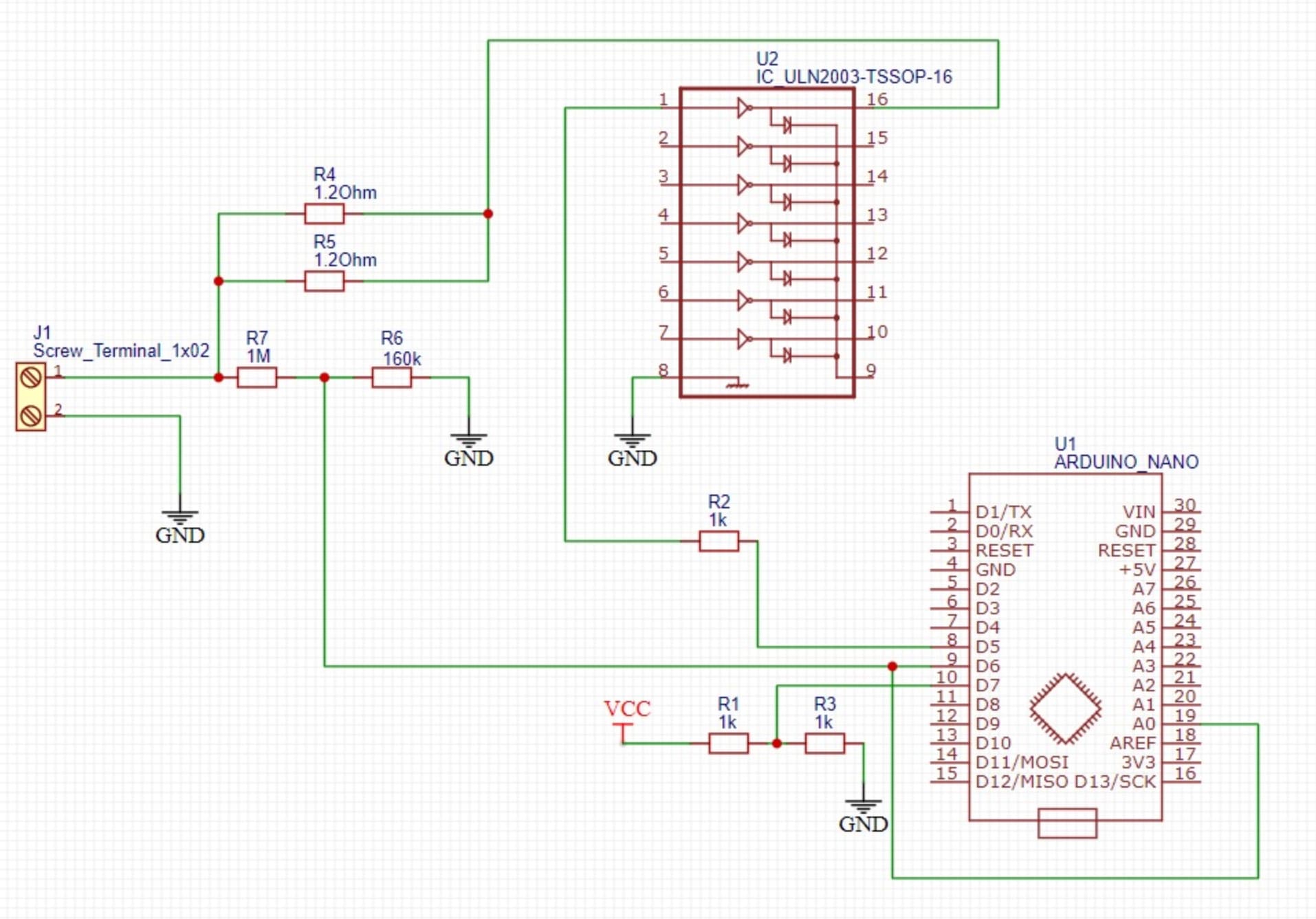
I'm struggling with powering it off the intercom wires now. The intercom system is just two wires, that have about DC 25V on them, fluctuating down to about 20V when messages are being sent. After some googling I figured I would try using a L7805CV to bring that down to a stable 5V and power my Arduino Nano RP2040 Connect through VIN and GND. Here's my circuit (apologies for the rough drawing):

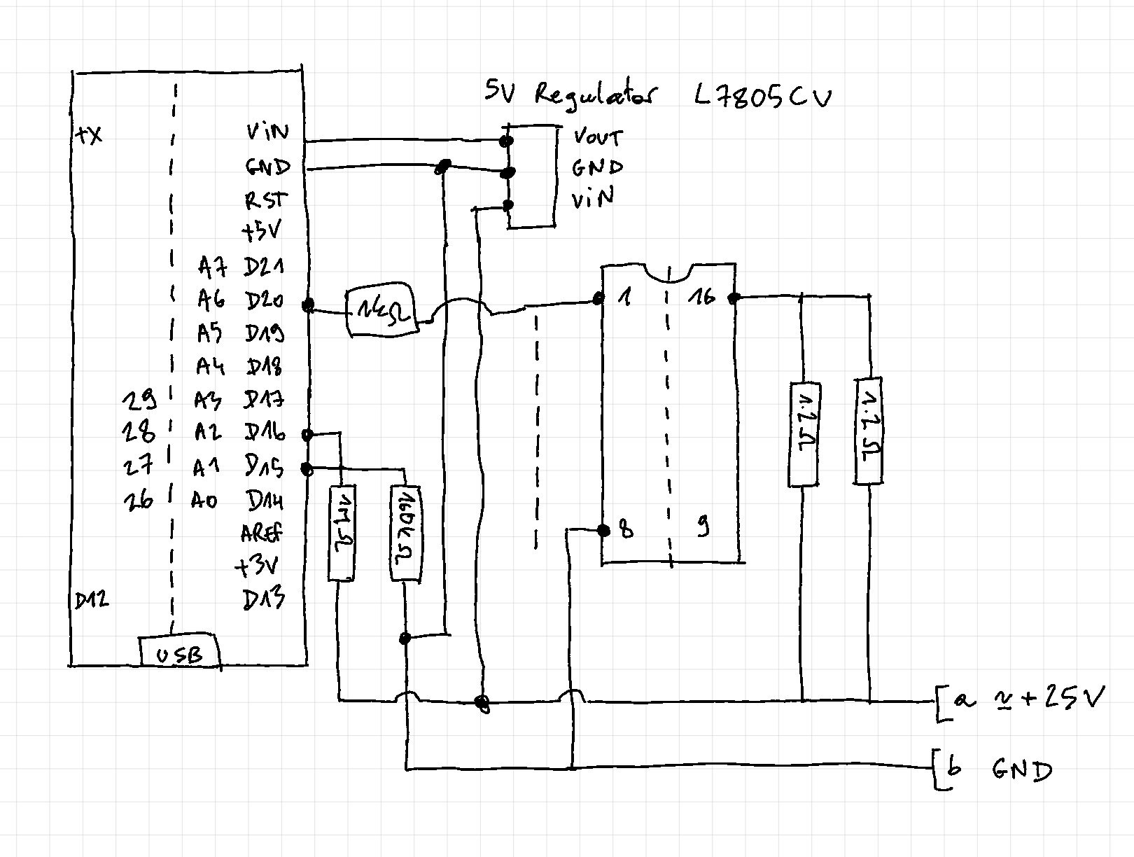
The big chip is a ULN2003L darlington array used to short the bus and send signals (I haven't gotten that part working yet). The entire circuit I took from the blog post linked above, I basically just added the 5V regulator.

My problem is that when I hook up my testing power source, which is a 12V wall-plug power brick from an old router, the Arduino power LED just blinks, and the Arduino never starts up.

If I measure with my voltmeter, I read 5V between (a) and (b) on the sketch above. So that's only 5V going into the regulator instead of 12V, and only about 3V coming out of it.

Is there anything obviously wrong that I'm doing ? I did just notice that the ULN2003 got quite hot in just a minute of powering the circuit. The Arduino and regulator are not warm. Am I supposed to use capacitors around my regulator ? I saw that suggested somewhere to stabilize the input, but here I'm running off a power brick, so I assumed it was pretty stable.

Any help is appreciated,

Thanks!

Paul

YES
See the data sheet for your specific manufacturer of 7805 because different manufacturers have different recommendations. Just because they have the same number, with this part the insides are different.

No it is not for that and having a stable input will not help. The capacitor is to stabilise the internal circuit of the regulator. They must be placed as close to the regulator as possible.

So disconnect the output of the regulator and try again.

That suggests a short circuit on the output or it is plugged in the wrong way round.

Thanks a lot for this Mike! Things are a bit clearer.

I take it from the datasheet that I need a 0.33 uf and a 0.1 uf capacitor. I'll go ahead and order those now.

I'll add them like so... does that seem right?

So disconnect the output of the regulator and try again.

So my voltage drop is simply a result of the load on the circuit and actually normal ? Sorry, this must be basic stuff, but I'm really a bit of a beginner. I read that regulator input has to be at least 2V above required output, so got worried that I won't be able to power my arduino. Arduino spec says 5-18V for input.

That suggests a short circuit on the output or it is plugged in the wrong way round.

What could "short circuit on the output" be ? A potential short of the output pins with an input pin ?

Thanks!

Yes that is right, apart from the fact that you should be feeding the output of the regulator to the 5V pin not the Vin.

That is only for the Vin or barrel jack input. That will then use the internal voltage regulator on the Arduino which is only good for about 150mA because of thermal matters. That is, it gets too hot and at best shuts down and a worst melts.

It could be the result of the load on your power supply but this is not normal. I suspect that there is some other fault further down the line that is drawing too much current.

There is an unmarked chip on your schematic with what looks like two 1.2R resistors in parallel going to pin 16. So that is potentially a load of 0.6R, which at a voltage of 24V will give a current of 24/0.6 = 40 Amps!
What is this chip? This could be the source of a large current drain from your power supply.

If you are usug

Hi Mike,

Thanks for the heads up about 5V input into arduino!

The unmarked chip is a ULN2003 darlington transistor array used to short the two incoming intercom lines. This is supposed to lower the voltage enough on the line so I can generate a "LOW" line code signal so I can send messages to the intercom. I pulled this entirely from this hackaday article and video.

EDIT: here's a better schematic of the circuit I'm trying to build that I found on the original blog post on hackaday:

First thing I noted is that there is an additional 1k resistor between the D5 on the Arduino and pin 1 of the ULN2003. I wonder if that's important.

If I understand this correctly, the Arduino should send a "HIGH" signal to pin 1 of the ULN2003, which will cause the ULN2003 to "short" pin 16 and pin 8 (ground), thus shorting our two inputs with only the two 1.2 Ohm resistors in between.

I must be misunderstanding something, though. The goal is to lower the voltage between the two inputs (1&2 on J1) from the normal 24V to about 20V to generate a "LOW" state. I'm not sure how R4 & R5 would achieve that.

No.

No time to watch low information content videos, but it seems like a totally different project to what you are doing. However, connecting an output almost directly to a 24V supply seems to be a rather stupid thing to do from my point of view. The 0.6R resulting resistor is nether here nor there, I would not be surprised if it exceeded the voltage rating of the chip. There is a big rule in electronics, never connect outputs together, and in this case an output is a power supply.

You have probably destroyed that pin, so move the circuit down one and use pins 2 & 15, and remove those stupid resistors.

Thanks a lot Mike!

To make sure I understand:

There is a big rule in electronics, never connect outputs together

Am I correct in assuming this is referring to connectors 1 & 2 of the Screw Terminal J1 in the schematic above, that are being connected together when the base of the Darlington transistor is HIGH? They are essentially being shorted with just a 0.6 Ohm resistor, and that's a no-go ?

The intention is to lower the 24V voltage between terminal connectors 1 & 2 to about 20V, for short pulses of about 4ms (these end up being 1-0 bits of the message on the bus). Assuming this alternative above is no good, how could one go about this ?

Thanks a lot!

No matter what is on the input it is still wrong.

Correct no good.

Go about what? Exactly what are you trying to do?

Go about what? Exactly what are you trying to do?

My bad, sorry for the lack of detailed background, here it goes:

I'm building a remote control for my apartment building's intercom system, which would allow me to receive notifications on my phone when someone rings the building door, and for me to remotely open that door.

The Arduino does all the online magic, I just need to get it to talk to my intercom.

My flat has an intercom "phone" with a door opening button like this:

This phone is connected to a module downstairs, and they talk to each other to receive calls / open doors, etc... through a 2-wire bus system.

With the help of that hackday post I posted earlier, I was able to decode some messages on that bus. The protocol is a "line code", with HIGH states being about 24V and LOW states being about 20V. The signal keeps alternating HIGH/LOW. Ones and zeroes are encoded with the pulse length, 2ms for zeroes and 4ms for ones.

Here's what a message looks like on the oscilloscope, plugged into terminal 1 & 2 in the schematic above. You can see some very long gaps that are message start/end signals, short gaps for ones and very short gaps for zeroes.

I got the reading part working, which is simply a voltage divider to bring the voltage < 3V so that I may read it with the Arduino's analog input. I wrote some code to parse the protocol described above and can now detect when someone rings our doorbell (and everybody else's for that matter, since there is one bus for the whole building, different doorbells have different "addresses").

Now the part I'm trying to crack is how to send messages on this bus. I have to be able to lower the voltage of these input terminals 1 & 2 from the normal 24V down to 20V. Once I can do that I just need to do it at the right frequency & intervals to send the "door open" message.

So this is what I'm trying to figure out, is this darlington transistor technique (which I got from the blog post) not a good option? And if not, how else would I go about this.

I am more of a software guy, so I'm a bit at a loss here. I really appreciate this help!

Best

Paul

that is the key to understanding this problem.

It is likely that this bus is what is known as a wired OR configuration, similar to the way an I2C bus works. That is to send out this signal to the bus you do not have to supply it with 24V, that is just the normal state of the line, generated in the intercom by a power source in series with a resistor. With no load on this line you will just see a 24V voltage level.

However if you connect a resistor of a certain value to ground, that will form a potential divider with the series resistor in the intercom, with the result that the voltage on the line drops down to 20V.

Now that is easy enough to do the trick is knowing the right resistor to use. To do that I would wire the signal line with a 10K resistor to ground and then measure the voltage on the line. Then by using ohms law you can calculate the value of resistor inside the intercom. Then knowing that you can calculate the resistor required to pull the line down to 20V, again by ohms law.

Now check that the Darlington driver can cope with that current, it can cope with anything under 500mA.

Then to get it working remove those two 1.2 ohm resistors, and connect the resistor you calculated to the output of your Darlington driver, with the other end to the 24 V signal rail and drive the input of your driver direct to the Arduino pin.

That is very similar to what you have already and I guess that your 1.2 ohm resistors is a misreading of the real value. Resistor R2 is a mistake as well, so connect that Arduino pin directly to the Darlington.

As a final note if you are sending stuff down a line that is normally driven by other peoples intercoms you might have trouble if two people try and signal at the same time.

Ok, now I think I get it! I was wondering how this thing works, but the voltage divider thing with the resistor in the other unit makes sense!! I should be able to figure it out now.

Thanks a bunch!!

This topic was automatically closed 180 days after the last reply. New replies are no longer allowed.