Powering up 30 LEDS externally / school carnival

Hello fellas,

I'm sure this has been asked a million times and I apologize in advance.

Might be a silly question, although I was curious if this is a proper way to drive 30 LEDs with an external supply.

I currently have 30 LEDs total with 2 LEDs per output/contact to the transistor, making use of 15 pins on my Mega.

The reason I ask is when I simply use the external supply and have the arduino NOT hooked up to my PC, the arduino resets every now and then when all LEDs are illuminated...

I can also see on the VIN (5v out from the motor driver is powering up the arduino) that it dips slightly below 4v when the reset is happening.

Do I need a bigger resistor on the base pin of the transistor?

I am working on a school carnival game for the kids' school.

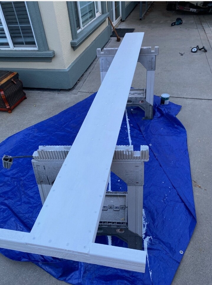
Here is the project so far!

(Sorry if the wiring/stuff is hokey, I plan on putting a back plate on the backside.)


Here is a rough schematic (I have 30 LEDs wired up like this // 2 LEDs on one arduino pin to transistor) --

Here is the code --

//led high striker game
//references to code used and help//documents
//psi math reference -- 'https://www.youtube.com/watch?v=UrqPxwsPWGk'
//led loops -- 'http://ece.uprm.edu/techcarnival/highstriker.html#video'
//L298N driver -- 'https://circuitsgeek.com/guides-and-how-to/arduino-dc-motor-control-using-l298n-motor-driver/'
//original idea (site appears to have issues now?) -- 'http://www.jmillerid.com/wordpress/2009/09/mustache-themed-hi-striker/'

int standby = 0;
int ledz = 0; // led loop init integer
float difficulty = 0.0; //difficulty variable
float difficultyValue = 0.0; // if difficulty is raised
unsigned long startMillis; //millisecond counter start value
unsigned long currentMillis; // millisecond current value
const unsigned long period = 500;  //millisecond period length
const float pressureZero = 103.55; //reading of pressure transducer at 0psi
const float pressureMax = 921.60; //reading of pressure transducer at 30psi
const float pressuretransducermaxPSI = 30.00; //psi value of transducer being used
float pressureValue = 0.0; //variable to store the value coming from the pressure transducer
float psiMaxVal = 0.005; //stores the psi max value after being compared // anything > 0 for boot up

void setup() {
  
  Serial.begin(9600); //begin serial for output window
  pinMode(LED_BUILTIN, OUTPUT); //turn on the on-board led
  
  for(ledz=39; ledz<=53; ledz++){ //for arduino di contact 39 to 53 // being used for led display
      pinMode(ledz, OUTPUT); //loop and set the outputs of the contacts
  }
  
  for(ledz=2; ledz<=7; ledz++){ //contact 2 is bell, 4 is ready status, 5/6/7 is difficulty knob, 3 not used
    pinMode(ledz, OUTPUT);
  }
}
 
void loop() {

  currentMillis = millis(); //set cur millis to internal millis clock

  //psi sensor math
  pressureValue = analogRead(A3); //reads value from sensor input pin and assigns to variable
  pressureValue = ((pressureValue-pressureZero)*pressuretransducermaxPSI)/(pressureMax-pressureZero); //conversion equation to convert analog reading to psi
  difficulty = analogRead(A0) * 3.0 / 1024.0; //difficulty zero pot

  //debug psi input
  Serial.print(pressureValue); //prints value to serial
  Serial.println(" psi"); //prints egu to serial
  //Serial.println(analogRead(A3));

  //debug difficulty
  //Serial.println(pressureValue + difficultyValue);
  
  //debug diff zero pot
  //difficulty zero pot input
  //zero pot on +3v output 0/1/2 for ranges
  //Serial.println(analogRead(A0) * 3.0 / 1024.0);
  //Serial.println(" ZERO POT");

  Serial.println(standby);

  if(pressureValue >= psiMaxVal + 0.2){ //if psi curr val is greater than psi max (+ a little offset) then set MAX
    
    psiMaxVal = pressureValue; //set max variable
    digitalWrite(4, LOW); //turn status led off // not ready for next hit
    startMillis = currentMillis; //set the start of the milli counter for 0.5s reset

    //debug psi max
    Serial.print(psiMaxVal);
    Serial.println(" psi MAXX"); 
  }
  
   if ((currentMillis - startMillis >= period) && (psiMaxVal != 0)){ //Reset psi max after 0.5s and if psi max is not zero

    psiMaxVal = 0; //clear out psi max variable
    digitalWrite(4, HIGH); //turn status led on // ready for next round
   
    //debug ready status
    //Serial.println("READY");
  }
  
  if ((difficulty >= 0) && (difficulty < 1)) {
    digitalWrite(5, HIGH);
    digitalWrite(6, LOW);
    digitalWrite(7, LOW);
    difficultyValue = 0;
  }
  else if ((difficulty > 1) && (difficulty < 2)) {
    digitalWrite(5, HIGH);
    digitalWrite(6, HIGH);
    digitalWrite(7, LOW);
    difficultyValue = 1;
  }
  else if (difficulty > 2) {
    digitalWrite(5, HIGH);
    digitalWrite(6, HIGH);
    digitalWrite(7, HIGH);
    difficultyValue = 2;
  }

//review psi max
  if (psiMaxVal > 5 + difficultyValue){
    ledzUP(53);    
    ledzDOWN(53);
  }
  else if (psiMaxVal > 4.5 + difficultyValue){
    ledzUP(51);
    ledzDOWN(51);
  }
  else if (psiMaxVal > 4 + difficultyValue){
    ledzUP(50);
    ledzDOWN(50);
  }
  else if (psiMaxVal > 3.5 + difficultyValue){
    ledzUP(48);
    ledzDOWN(48);
  }
  else if (psiMaxVal > 3 + difficultyValue){
    ledzUP(46);
    ledzDOWN(46);
  }
  else if (psiMaxVal > 2.5 + difficultyValue){
    ledzUP(45);
    ledzDOWN(45);
  }
  else if (psiMaxVal > 2 + difficultyValue){
    ledzUP(43);
    ledzDOWN(43);
  }
  else if (psiMaxVal > 1.5 + difficultyValue){
    ledzUP(41);
    ledzDOWN(41);
  }
  else if (psiMaxVal > 1 + difficultyValue){
    ledzUP(40);
    ledzDOWN(40);
  }
  else if (psiMaxVal > 0.5 + difficultyValue){
    ledzUP(39);
    ledzDOWN(39);
  }
  
  //dance ledz when zero pot is turned down all the way
  if ((difficulty >= 0) && (difficulty < 0.1)) {
    ledzUP(53);
    delay(2000); //delay at the top so blink leds can "show better"
    ledzDOWN(53);
    delay(250); //delay at the bottom
    standby = 1; //standby flag to not ring bell
  }
  else{
    standby = 0; //turn standby off
  }
}

void ledzUP(int x){
  if(x < 39){
    return;
  }
  else{
    ledzUP(x-1);
    digitalWrite(x, HIGH);
    delay(100);
    if((x >= 53) && (standby == 0)) {
      //ring bell
      digitalWrite(2, HIGH);
      delay(1000);
      digitalWrite(2, LOW);
    }
  }
}

void ledzDOWN(int x){
  if(x < 39){
    return;
  }
  else{
    delay(100);
    digitalWrite(x, LOW);
    ledzDOWN(x-1);
  }
}

A few points --

I hope the code comments make sense, but I am using a psi xducer to measure a "hit" and drive some LEDs up and then ring a bell.

Original idea and code/references are in the code at the top.

I have a zero pot to adjust the "difficulty" of the game.

I'll try to get a schematic drawn up for further assistance.

I understand I'm not really using the motor driver properly/as intended. Was hoping to just try one out and see what it does.

My code may not be the best, but it's working as I would like!

Any advice helps!

Why do you need 2 transistors for 2 LEDs ? Why not a single transistor for the pair? You will half the current you are pulling through the Arduino.

If you have any hope of catching the peak you need to run the loop() as fast as possible. That means not printing in the loop() while waiting for a hit. I suggest that you read up on state machines. Have a part where you are waiting, then when the hit happens do the calculations, output to the LEDs, print and clear the LEDs after the timeout.

You are put an unnecessary high load to the I/O pins and are current-wise overloading the Mega.
To my knowledge, the Mega is driven by 5V, so you get 2*(5V-0.7V)/220R = 39mA load current for one I/O - this is already at the limit of an I/O pin (40mA). Multiplying this with 15 total load on Mega is 0.6A ... this will not work.

Increase the base resistor. With a assumed DC gain of a small signal transistor (check data sheet of the one you use) of 100 a base resistor of (5V-0.7V)/(0.013/100) = 33k is sufficient (you may use also a little smaller resistance, e.g. 27k).
Base current is then 0.013A/100 = 130uA, which will not overload IO and in total not the Mega.

void ledzUP(int x){
  if(x < 39){
    return;
  }
  else{
    ledzUP(x-1);
    digitalWrite(x, HIGH);
    delay(100);
    if((x >= 53) && (standby == 0)) {
      //ring bell
      digitalWrite(2, HIGH);
      delay(1000);
      digitalWrite(2, LOW);
    }
  }
}

Oh. ledzUp(int x) is calling recursivly ledzUp(int x). Up to 14 times, right? (for LED 39 to 53) - Are you aware of this? It is consuming memory, but with simple function ledzUp and memory resources on a Mega most likely not an issue ...
Also this code is blocking, which is usually a bad coding style (see comment of @groundFungus) but ... this blocking may(!) provide desired functionality that subsequent hits are ignored once one has been detected. Not sure if your would behave like this, I haven't looked all through.

Well, not in case base resistor is selected just to drive a single LED. So twice the base current for two LEDs - no saving in output current for I/O. Nevertheless, it would simplify the wiring - but it seems that this is done already ... so @200mV may stick to his solution to avoid rework.

1 Like

Hi,
Do you have a DMM?

Tom.. :smiley: :+1: :coffee: :australia:

Morning fellas, and thanks for the replies!

My original plan was to address all LEDS individually (separate pins).

When it came to wiring it down to the arduino, I landed the wires as shown.

I understand I only would need 1 transistor for both LEDs if I kept it in the current state.

I may re-land all LEDs separately.

What is strange about this is, when I do run the loop without any prints, I miss the peak and the print seems to help "catch" it. Haven't really gotten to the bottom of it, but the hits are caught and seems to run pretty good as it is.

I'll take a look at the state machines link, thanks!

Thank you, this is what I believe I need. I overlooked this calc when wiring up the transisors.

Appreciate the reminder on the cut off. :slight_smile:

This is correct, I only need to capture one hit at a time and when the loop is finished and a 500ms timer is finished, I clear out the last "maxPSI" so to capture it again.

I do...

Thanks for all the replies :slight_smile:

1 Like

Just wondering...

Is the transistor a MOSFET?

I believe when you apply even a very low voltage to a MOSFET (so you can have high-value resistors), the MOSFET will turn on completely. I may be wrong, as I am not an expert in MOSFETs and whatnot.


Have you heard of NeoPixels (or WS2812B LEDs)?


Another random question...

Why are you using a motor driver for the bell?

@anon44338819

Hello, they are just BJT :slight_smile:

See my comment in the "Note" area I made.

I understand I don't really need a motor driver in this situation, I wanted to do 2 things --

Try one out for fun and use the 5V out to power up the arduino (less power supplies running around)

:slight_smile:

Man, this would have saved some time! HA! Cool thing, thanks for the link.

Is the diagram correct, in that you are feeding the 5V line from the motor driver into Vin of the Mega? That does not seem right.

That is correct, the 5V is out from the driver to VIN on arduino.

The minimum requirement for Vin is 7V so you're using the board out of spec. 5V should go to the 5V pin.

Be careful, it's not advisable to power on both the 5V and USB at the same time. During development, power the LEDs from the 5V of the motor driver and use the USB to power the Arduino; once you no longer need the USB, power the board from the 5V of the motor driver.

Thanks for that, did not know it was a dual purpose contact!

Is there any special requirements before landing the wire to the 5V pin?

You are completely wrong.

You should use a much bigger resister on the base of the npn, if it is an npn.
Having low resistors there, 15 on all at once would draw more current (total) out of the pins than your arduino can supply, so it glitched off.

Some things which you need to look up or test are : LED datasheets; V_on at max rated current, and I_on maximum rated current. Those are different for different LED types. Test each colour seperately. I'll start with a guess of 2V 20mA reds, 3V 20mA blues, and revise these numbers with datasheet values for what you've got. Between the LED+ and the +5V supply, you'd get it brighter on the blues with about 100 Ohms, but for reds you should choose more than that to keep it down near (20mA) when testing without the transistor. Consider trying series-pairs of LED such as GND-npn-green-green-smallR-5V. I think that will work with two reds and 40 Ohms to 5V, it might work with two greens, and I have doubts about two blues working from 5V.

I'd use a 7.2V twin lithium battery instead of the "5V 3A".
Then it could be GND-npn-blue-blue-33Ohms-7.2V and larger R are somewhat better for the other colour LED. The npn base still gets 5 or 4.5 Volts from the arduino. The npn takes any remaining Volts on its main path not used up by the resistor and LED's, so battery variation from about 8V to 7V is almost entirely taken up with an extra Volt on the npn, which is supposed to be letting through constant current = gain x I_base.

Next to calculate your base resister size. Datasheets help. Find gain 'beta' of the npn transister. If you don't know then test. If +5 Volts 'signal' to base, which you can test on pinboard, what size of resister results in 20mA going through the main path of the transister? If you don't know then start with a guess of beta=100. 20mA/100 = 0.2mA at 5 Volts. R_base could be 25kOhms. Nearest common value rounded down is 22kOhm. It won't hurt to try 10k or 47k or 33k - see what gets the LED bright enough for what you are doing and round down.

Lastly, and you could find this out from the datasheet, or from test, some npn have middle leg base, and a few types swap the legs around. If you cannot find the datasheet then measure gain 'beta', either on pinboard or on the better type of multimeter. For example, getting the two n's swapped around by mistake it might seem to work but with less gain than the right way around. If you'd poked around with different signal to base resistors until something lit up, it would be possible to have got some transistor legs the wrong way around. Pinboard is the right way to test against that.

1 Like

I thought so.

Drain current vs. gate bias is roughly an exponential function.

Thanks much to all who replied.

Swapped the 220 ꭥ resistors with 22k ꭥ resistors to the base pin of each transistor.

Essentially removed 100x the load off the arduino.

Ran the game in "standby" for several hours without 1 reset of the arduino. :partying_face:

I may tune the code more or possibly separate out each LED in an attempt for more "led dancing" routines, alas time is always not in my favor.

Again, appreciate the feedback!

This topic was automatically closed 180 days after the last reply. New replies are no longer allowed.