So, i have a project to do, a proportional pressure regulator that contains 2 proportional valves controlled with PWM, the problem is that i don't really have any experience using arduino, but from my reseach this seems the easiest way to reach my target. On short, i need the pressure on the outlet of the pressure regulator (measured with a pressure sensor) to be the same with a preseted signal, for that i use the 2 proportional valves , 1 for inlet the pressure if the pressure its lower than the set value, and one to exhaust the pressure if the pressure its higher than the set value. The electromagnets inside the valves need to be powered with 12 V for opening the respective valve. What i need from you guys its to give me some ideea of what parts i need and if this is possible to be done with around 100$ budget. Thank you all for helping me and sorry for my writing, english its not my first language.
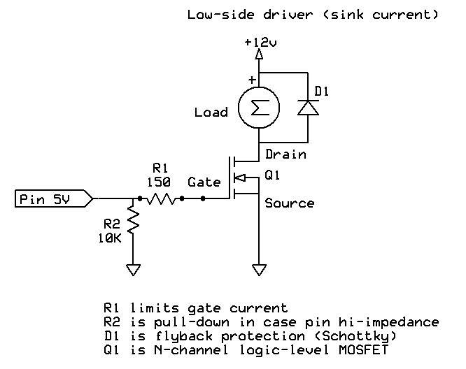
That's doable. You can use logic level N channel MOSFETs switching the low side of the electromagnets.
180 ohm between the MOSFET gate and the controller, 10 kOhm from gate to GND.
What kind of controller do you recommand?
Easily done with a Uno. Shields fit on it easily. Nano is the same, but smaller form factor if space is a concern.
Do you understand how pressure regulators regulate pressure? Doesn't seem so. They regulate by RELEASING more flow or reduce the flow. They do not work in tandem that way you have described.
How i said,english its not my first language, my valve use a plunger to move the plain poppet seat, the poppet blocks the outlet orrifice of the valve with the tension from a spring, the plunger its attracted by the electromagnet and it rises the poppet , and the flow can pass trough. In simulation i managed to do this by using PID for the inlet valve and compare the set signal with the actual pressure ,if higher then the outlet valve its oppened. Please correct me if i made any mistake
IF pressure is higher, you need to keep the inlet valve closed for a longer period of time and that one valve will do the regulation,
No, I'm on the same side as @Railroader , from gate to GND,
Why would you think that? 
If the transistor is somewhat far from the gate resistance, the cable or union track can behave as a small capacity that I don't know why it can be charged, leading the transistor to a total or partial conduction. The closer the TR and its resistance to the GND, the better.
Regarding the voltage dividing effect 180/10k makes no significant loss of gate voltage when active. Pulling the gate low if output is high z will also work fine.
Did your simulations show that you system will oscillate wildly when the two pressures are close to the same value?
It does not, it barelly oscilates with a range of 0.0001 bar, regardin your previous answear, you can't lower the pressure in a system just by closing the inlet valve, pressure it's not a consumable, it won't dissapear just because you blocked its source, you may think about proportional electromagnets, that can have positions between full open and full closed, but mine are normal electromagnets, who can be use in "all or nothing" positions, thats why i need to use PWM to control them

Ah well, that makes no sense to me I am afraid.
I am always referring to the OUTPUT pressure. You can use PWM to a single valve by varying the width.timing of the on pulse as well as the off pulse times.
So what are you saying its that i can use one single valve by varying the voltage that goes through the electromagnet with PWM and modifing the pull force of the electromagnet this way,without reaching values higher than the desired one?
No, not varying the voltage or the current, ONLY the open/close times! That will produce the exact same result as the spring-loaded mechanical pressure regulator that everyone uses now. The mechanical regulators vary the spring pressure to vary the output pressure and your device will accomplish an identical result by changing the on/off ratio. Due to the inertial of the solenoid, the result will be a steady pressure, at some point.
The one issue I foresee is that there is likely to be some hysteresis and non linearity in operation if you use them with fast PWM to control how far open they get ; which might make life difficult - you might be better off with valves simply controlled by motors.
Operating them relatively slowly so they go fully open during pulses will need a big volume between and after the valves for smoothing and make control very difficult . They will wear out quickly too !
Before you get into coding , just vary the voltage to the valves and see how well they function .
BTW if you google I/P converters they use valves the size of Reed switches to to load a regulator
Your other topic on the same subject deleted.
Please do not duplicate your questions as doing so wastes the time and effort of the volunteers trying to help you as they are then answering the same thing in different places.
Repeated duplicate posting could result in a temporary or permanent ban from the forum.
Could you take a few moments to Learn How To Use The Forum
It will help you get the best out of the forum in the future.
-
Your OS and version can be valuable information, please include it along with extra security you are using.
-
Always list the version of the IDE you are using and the board version if applicable.
-
Use quote or add error messages as an attachment NOT a picture.
-
How to insert an image into your post. ( Thanks @sterretje )
-
Add your sketch where applicable but please use CODE TAGS ( </> )
-
Add a SCHEMATIC were needed even if it is hand drawn
-
Add working links to any specific hardware as needed (NOT links to similar items)
-
Remember that the people trying to help cannot see your problem so give as much information as you can
COMMON ISSUES
-
Ensure you have FULLY inserted the USB cables.
-
Check you have a COMMON GROUND where required. ( Thanks @Perry)
-
Where possible use USB 2.0 ports or a USB 2.0 POWERED HUB to rule out USB 3.0 issues.
-
Try other computers where possible.
-
Try other USB leads where possible.
-
You may not have the correct driver installed. CH340/341 or CP2102 or FT232 VCP Drivers - FTDI
-
There may be a problem with the board check or remove your wiring first.
-
Remove any items connected to pins 0 and 1.
COMPUTER RELATED
-
Close any other serial programs before opening the IDE.
-
Ensure you turn off any additional security / antivirus just to test.
-
There may be a problem with the PC try RESTARTING it.
-
You may be selecting the wrong COM port.
-
Avoid cloud/network based installations where possible OR ensure your Network/Cloud software is RUNNING.
-
Clear your browsers CACHE.
-
Close the IDE before using any other serial programs.
-
Preferably install IDE’s as ADMINISTRATOR or your OS equivalent
ARDUINO SPECIFIC BOARDS
-
CH340/341 based clones do not report useful information to the “get board info” button.
-
NANO (Old Types) some require you to use the OLD BOOTLOADER option.
-
NANO (ALL Types) See the specific sections lower in the forum.
-
NANO (NEW Types) Install your board CORE’s.
-
Unless using EXTERNAL PROGRAMMERS please leave the IDE selection at default “AVRISP mkII”.
-
Boards using a MICRO usb connector need a cable that is both DATA and CHARGE. Many are CHARGE ONLY.
CREATE editor install locations.
-
On macOs ~/Applications/ArduinoCreateAgent-1.1/ArduinoCreateAgent.app/Contents/MacOS/config.ini
-
On Linux ~/ArduinoCreateAgent-1.1/config.ini
-
On Windows C:\Users[your user]\AppData\Roaming\ArduinoCreateAgent-1.1
Performing the above actions may help resolve your problem without further help.
Language problem ?
Try a language closer to your native language:
Thanks to all those who helped and added to this list.