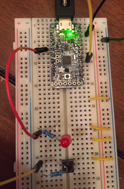
Would anyone be able to modify the Arduino Button Example program to work for Pro Trinket? Button 2 is used in the original code and I'm either inputting the code wrong when I change it to be pin 3 or I have wire issues. I'm just trying to learn so just knowing the code is good for what I have (Pro Trinket) would be very helpful. Thank you!!
/*
Button
Turns on and off a light emitting diode(LED) connected to digital
pin 13, when pressing a pushbutton attached to pin 2.
The circuit:
LED attached from pin 13 to ground
pushbutton attached to pin 2 from +5V
10K resistor attached to pin 2 from ground
Note: on most Arduinos there is already an LED on the board
attached to pin 13.
created 2005
by DojoDave http://www.0j0.org
modified 30 Aug 2011
by Tom Igoe
This example code is in the public domain.
*/
// constants won't change. They're used here to
// set pin numbers:
const int buttonPin = 2; // the number of the pushbutton pin
const int ledPin = 13; // the number of the LED pin
// variables will change:
int buttonState = 0; // variable for reading the pushbutton status
void setup() {
// initialize the LED pin as an output:
pinMode(ledPin, OUTPUT);
// initialize the pushbutton pin as an input:
pinMode(buttonPin, INPUT);
}
void loop() {
// read the state of the pushbutton value:
buttonState = digitalRead(buttonPin);
// check if the pushbutton is pressed.
// if it is, the buttonState is HIGH:
if (buttonState == HIGH) {
// turn LED on:
digitalWrite(ledPin, HIGH);
} else {
// turn LED off:
digitalWrite(ledPin, LOW);
}
}
Did you change: const int buttonPin = 2; to const int buttonPin = 3; ?
Did you change: * 10K resistor attached to pin 2 from ground to * 10K resistor attached to pin 3 from ground?
If you are using an external LED did you connect the cathode to GND, anode to current limiting resistor (330 to 680 Ohm), other end of resistor to pin 13?
Here is a picture and below is how I modified the code...external LED is on PIN 13 and works with builtin LED. Button is on pin 4.
/*
Button
Turns on and off a light emitting diode(LED) connected to digital
pin 13, when pressing a pushbutton attached to pin 2.
The circuit:
LED attached from pin 13 to ground
pushbutton attached to pin 4 from +5V
10K resistor attached to pin 2 from ground
Note: on most Arduinos there is already an LED on the board
attached to pin 13.
created 2005
by DojoDave http://www.0j0.org
modified 30 Aug 2011
by Tom Igoe
This example code is in the public domain.
*/
// constants won't change. They're used here to
// set pin numbers:
const int buttonPin = 4; // the number of the pushbutton pin
const int ledPin = 13; // the number of the LED pin
// variables will change:
int buttonState = 0; // variable for reading the pushbutton status
void setup() {
// initialize the LED pin as an output:
pinMode(ledPin, OUTPUT);
// initialize the pushbutton pin as an input:
pinMode(buttonPin, INPUT);
}
void loop() {
// read the state of the pushbutton value:
buttonState = digitalRead(buttonPin);
// check if the pushbutton is pressed.
// if it is, the buttonState is HIGH:
if (buttonState == HIGH) {
// turn LED on:
digitalWrite(ledPin, HIGH);
} else {
// turn LED off:
digitalWrite(ledPin, LOW);
}
}