Problem Implementing Complementary Filter

Hi,

I'm in the midst of a project where i need to use the gyroscope/accelerometer sensor MPU-6050. The project attempts to estimate the angle of the sensor using both the accelerometer and the gyroscope readings. The first characterised by stability over time and the second by short time stability with long time drift. I've therefore decided to try implement a complementary filter. I'm using Arduino nano.

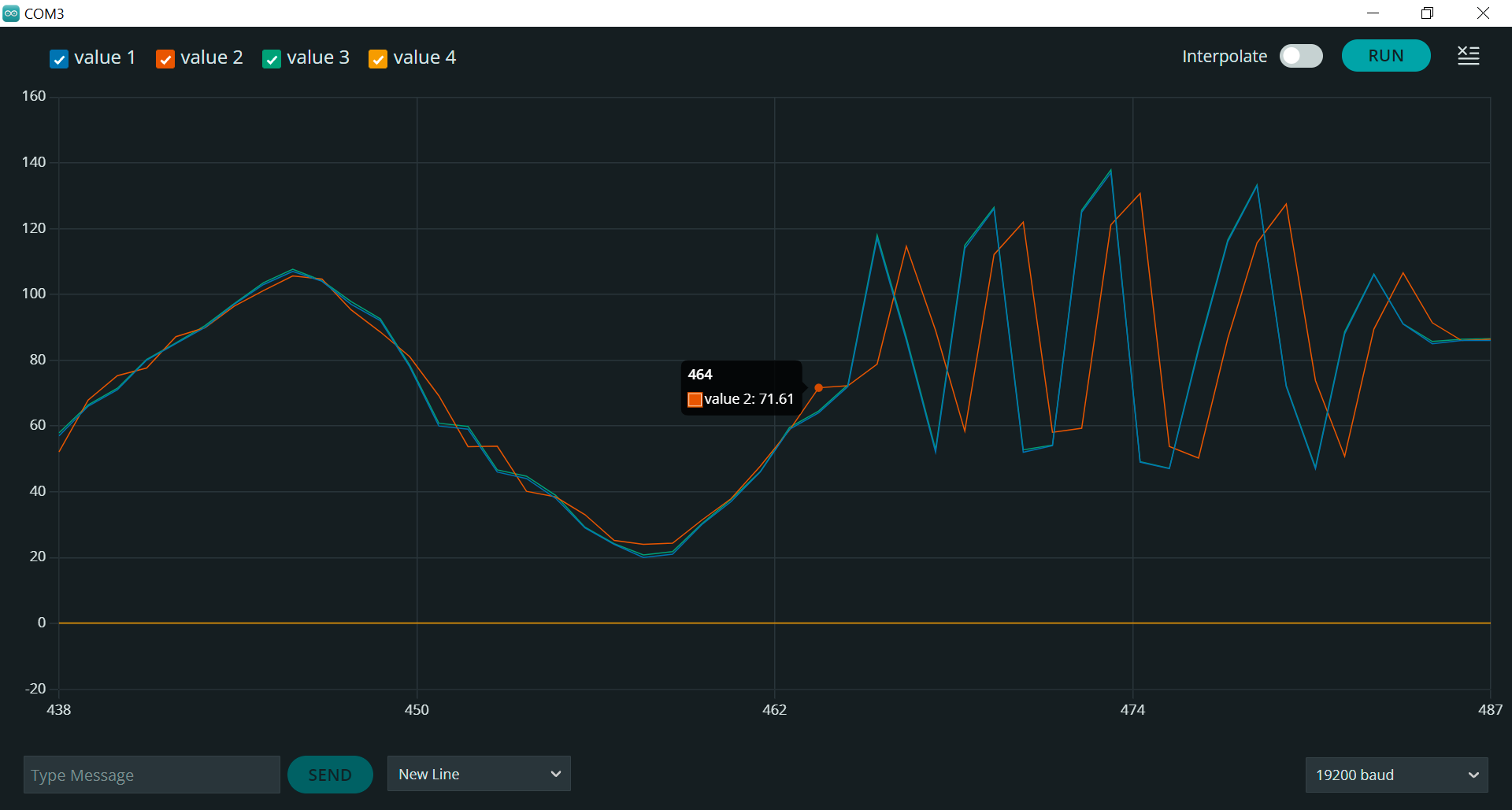
The problem I'm facing is that the complementary filter spits out values that seemingly show only accelerometer characteristics OR only gyroscope characteristics. I'm now fine tuning at the 11th decimal of the filter coefficient, which seems unreasonable. I judge the characteristics by watching the serial plotter while moving the sensor quickly from side to side, something that only affects the accelerometer angle estimation method.

I've tried:

  • At great length fine tuning the filter coefficient.

  • increasing diffTime (dt) using an if statement.

  • Relocating the time logic inside the loop.

Is there something I am missing? * I should also note that while I know there are complementary filter libraries, I would really wish to pursue this method, as it is something I want to know how to implement. I also excuse any language mistakes or failures in following post guidelines.

Link to MPU-6050 register map

#include <RH_ASK.h>
#include <SPI.h>  // Not actually used but needed to compile
#include <Wire.h>

RH_ASK driver(2000, 11, 4, 12);
uint8_t angleToSend;
uint8_t valueLength;

// Variables for gyroscope
const int Mpu = 0x68;  //I2C adress for coms
float accX, accY, accZ, angVelocityZ;
float angleApprox1, angleApprox2, currentAngle, tempAngle;

// Filter constant for complimentary filter, at value 0.99.....702 the filter potray only gyro characteristics!
// There seem to be a very distinct switch going from accelerometer to gyro behaviour.
const int filterConstant = 0.99999997015;

// Time variables
float currentTime, previousTime, diffTime;

void setup() {
  Serial.begin(19200);
  Serial.println("Serial OK");
  Serial.println("");

  Wire.begin();
  Serial.println("Wire OK");

  if (!driver.init())
    Serial.println("init failed");
  else {
    Serial.println("RH driver OK");
  }


  // Perform MPU signal reset
  Wire.beginTransmission(Mpu);
  Wire.write(0x6B);  // Talk to register 6B
  Wire.write(0x00);  // Reset - leaves calibration intact
  Wire.endTransmission(true);

  // Set the correct acceleration scale
  Wire.beginTransmission(Mpu);
  Wire.write(0x1C);        // Talk to register 1C
  Wire.write(0b00000000);  // Set scale to 2g, perform no self test
  Wire.endTransmission(true);

  // Make singular measurement to provide staring point for angular velocity approximation method
  Wire.beginTransmission(Mpu);
  Wire.write(0x3B);             // Start at register 3B
  Wire.endTransmission(false);  // Keep the I2C bus open
  Wire.requestFrom(Mpu, 6, true);

  accX = (Wire.read() << 8 | Wire.read()) / 16384.0;
  accY = (Wire.read() << 8 | Wire.read()) / 16384.0;
  accZ = (Wire.read() << 8 | Wire.read()) / 16384.0 - 0.1;

  // Calculate angle of sensor
  currentAngle = atan2(accY, -1 * accX) * 180 / 3.1416;
  currentTime = micros();
}

void loop() {
  // Get acceleration readings
  Wire.beginTransmission(Mpu);
  Wire.write(0x3B);             // Start at register 3B
  Wire.endTransmission(false);  // Keep the I2C bus open
  Wire.requestFrom(Mpu, 6, true);

  // Read 8 bits and store in 16 bit integer, shift to the left. The or operation overlays the next reading.
  accX = (Wire.read() << 8 | Wire.read()) / 16384.0;  // Division according to datasheet page 29, unit is [G].
  accY = (Wire.read() << 8 | Wire.read()) / 16384.0;
  accZ = (Wire.read() << 8 | Wire.read()) / 16384.0 - 0.1;

  // Get angular velocity around x-axis
  Wire.beginTransmission(Mpu);
  Wire.write(0x47);             // Start at register 43 (Hex)
  Wire.endTransmission(false);  // Keep the I2C bus open
  Wire.requestFrom(Mpu, 2, true);
  angVelocityZ = (Wire.read() << 8 | Wire.read()) / 131 + 5;  // Division according to datasheet page 31

  // Update time variables
  previousTime = currentTime;
  currentTime = micros();
  diffTime = (currentTime - previousTime) * 0.000001;

  // Use complementary filter
  angleApprox1 = currentAngle + angVelocityZ * diffTime;
  angleApprox2 = atan2(accY, -1 * accX) * 180 / 3.1416;
  currentAngle = filterConstant * angleApprox1 + (1 - filterConstant) * angleApprox2;
  tempAngle = currentAngle;

  // Constrain angle to 0 < angle 180
  if (tempAngle < 0 && tempAngle > -90) {
    tempAngle = 0;
  } else if (tempAngle >= -180 && tempAngle < -90) {
    tempAngle = 180;
  }
  angleToSend = int(tempAngle);

  // Send angle
  valueLength = sizeof(angleToSend);
  driver.send(&angleToSend, valueLength);
  driver.waitPacketSent();

  Serial.print(angleToSend);
  Serial.print(" ");
  Serial.print(angleApprox1);
  Serial.print(" ");
  Serial.print(angleApprox2);
  Serial.print(" ");
  Serial.println(diffTime);
}

Most likely, your definitions of the angle from the gyro rate and the accelerometer data are incompatible.

The following equation makes no sense to me. Please explain your thinking. I suggest to review this tutorial: How_to_Use_a_Three-Axis_Accelerometer_for_Tilt_Sensing-DFRobot

Since Euler angles have a number of serious problems, people have moved on to using quaternions to represent 3D orientation.

Thank you for your answer jremington!

I do believe the definitions of the angles are compatible. The code produces data that is in accordance with values you'd expect when tilting the sensor. This goes for both methods when tested separately, both producing values in degrees.

I excuse that I might have left out that I'm only interested in the tilting angle around one axis. Given this, the equation your looking at does exist in the resource you've provided, found under the headline "tilt angle"

→ acc_y/acc_x = - tanφ

Moving the negative sign and taking arctan gives

arctan(-acc_y/acc_x) = φ

Introducing the 180 / 3.1416 coefficient to convert from radians to degrees gives

arctan(-acc_y/acc_x) * 180 / 3.1416 = φ (deg)

Which when expressed in C code is

angleApprox2 = atan2(accY, -1 * accX) * 180 / 3.1416;

I'm inclined to believe that the problem lies elsewhere.

→ acc_y/acc_x = - tanφ

No.

The MPU-6050 can be used to measure only the two tilt angles with respect to vertical, the gravity vector.

The X and Y components of the gravity vector, which you are using in the offending equation, depend on those tilt angles, and not on the rotation about Z. That is, assuming the MPU-6050 has Z approximately vertical, but the argument holds for any vertical axis.

To measure yaw, the rotation about the vertical, most people use a magnetometer to give a yaw=0 North reference.

Thank you for your quick reply,

I will update the original description with information regarding sensor orientation. As of now, when holding the sensor in an upright position, I read 90 degrees. The range of interest span between 0 and 180 degrees.

The axis facing upwards is the y axis. We are interested in the tilt around the sensors z-axis (lying down). To obtain this tilt we approximate the angle of the gravity acceleration vector mirrored on the y and x axis respectively by using the two acceleration measurements along with the arctan function.

The minus sign could be moved out since arctan is an odd function, it only exist to make the angles positive in my specific arrangement.

Do NOT modify your original post. It makes the thread impossible to follow, and violates the forum rules.

Noted.

Hi again,

I've tried to clarify my situation somewhat. The pdf presents the orientation of the MPU 6050 as soldered on as well as my mathematical reasoning.

The two pictures show measurements from the sensor. The first picture shows the output with a very high filter coefficient. Blue line is the output angle, red line is angleApprox1 and green line is angleApprox2. The right hand side of the picture is me shaking the sensor side to side. While accelerometer measurements show large interference, the output value remain good! However the line, as can be seen, starts to drift upwards.

The second picture shows a coefficient where the accelerometer dominates. Same colors apply. No drift but very large side to side interference.

Once again, the issue seems that no matter how carefully I adjust the filter coefficient, the switch between the behaviours is seemingly binary.

MOU 6050 Math.pdf (340.1 KB)

The "behavior switch" probably has to do with the expected round off error in floating point arithmetic.

32 bit float variables have at most 7 decimal digits of accuracy, so when subtracting this constant from 1.0, the difference is probably zero.

const int filterConstant = 0.99999997015;

I still think that the two angle estimates are incompatible and a weighted average will simply give nonsense.

Hmm, I just noted that filterConstant is declared int. So, it is in fact equal to zero.

All bets are off now.

Hi again!

I'm not sure I understand what you mean by incompatible. Could you elaborate?

I'll try the gyro method separately without the feedback from the filter and only give it an initial angle value. I figure if the measurements method then align in the plotter they ought to be compatible?

oooh, I'll get right to it.

Conflicting signs, for example. The measured rate of rotation has a sign, as does the tilt angle estimate.

It seems the int data type was the issue, switching it to a const float got the filter working!

I see. I do see that the filter fails when I tip over at 0 or 180 degrees. I'll investigate and try to resolve these issues tomorrow. For now I thank you for your help!

Unavoidable, and one of the reasons most people have switched to quaternions.