I have a four channel relay(RAS-0510) module,it has 7 pins namely Vin,Gnd,Gnd,Ip1,Ip2,Ip3,Ip4,as in case of most of the relay modules they have two supply pins namely Vcc and JdVcc but in my relay module there is no pin called JdVcc and also my module has only one supply pin Vin and there are two ground pins.I am a bit confused in connecting the supply and ground pins to the arduino UNO and also should i connect both ground pins to arduino ground pins?.Please help me out.
I have a four channel relay(RAS-0510) module,it has 7 pins namely Vin,Gnd,Gnd,Ip1,Ip2,Ip3,Ip4,as in case of most of the relay modules they have two supply pins namely Vcc and JdVcc but in my relay module there is no pin called JdVcc and also my module has only one supply pin Vin and there are two ground pins.I am a bit confused in connecting the supply and ground pins to the arduino UNO and also should i connect both ground pins to arduino ground pins?I have attached the pic of relay module.Please help me
Thanks in advance
Regards,
vsbhat
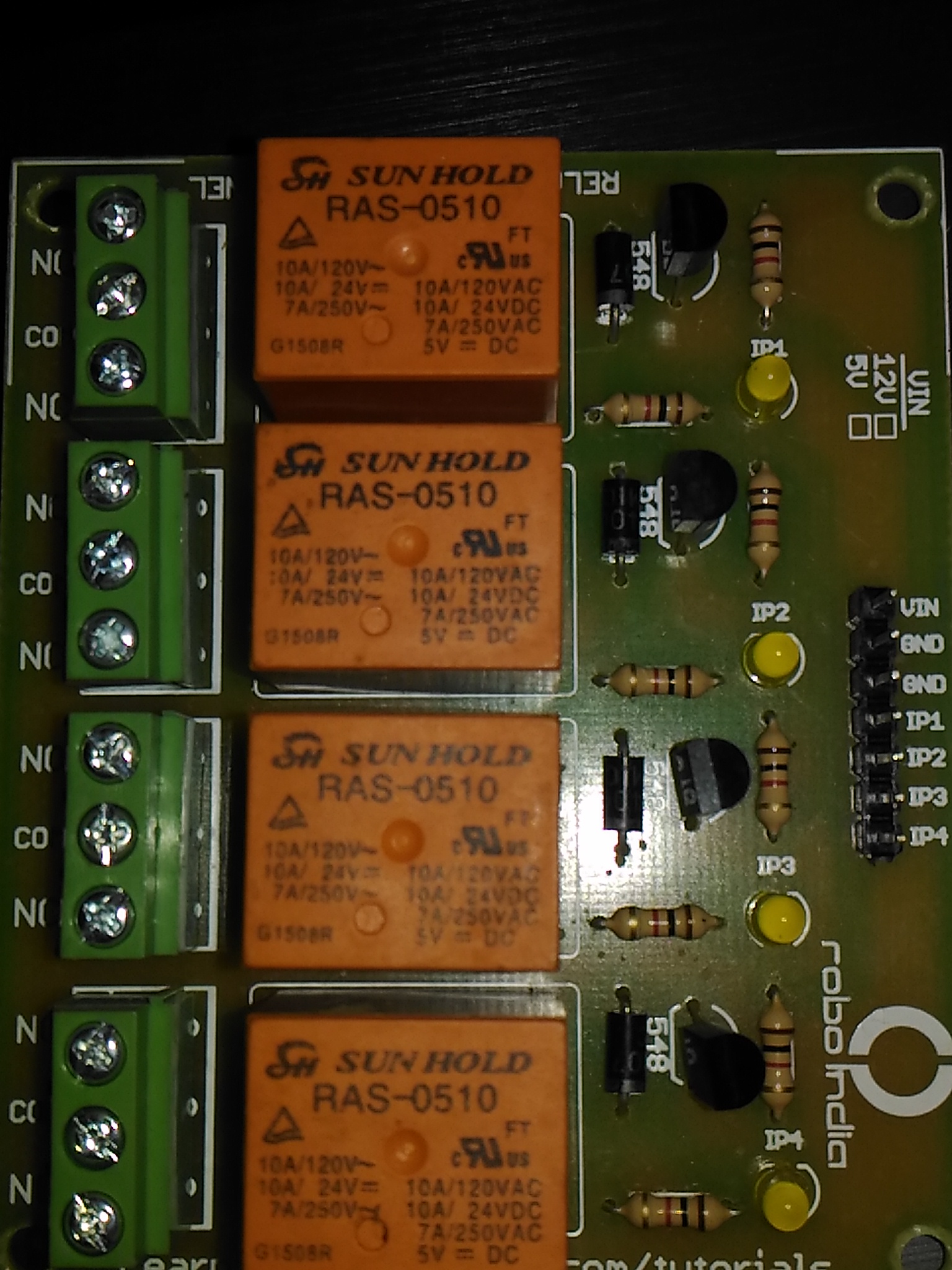
That part number seems to be just the bare relay itself. Can you give us a link to the actual board you bought?
At least the manufacturer's name is shown on the board. They seem to have a very extensive website with good tutorials. Their relay tutorial doesn't help?
I can't find the actual product on the site though. So I can't confirm how it works. I expect that both ground pins are connected on the board, so you don't need to connect them yourself. It just allows you to connect two pins for the power supply and then there's a spare pin to connect the Arduino's ground. (You should probably run the Arduino from the same power supply.)
jdVCC is normally on relay boards that use optocouplers, yours is just a direct transistor driver so you simply connect a +5v to Vin.
The 2 GND points, if you look at the pcb track, feel sure they will be commoned up.
Theres 2 to you can have the GND from its power supply the Ardunio GND connected to it
Ideally you should use a separate + 5v and GND for the relay board to help avoid noise / voltage drop getting back on to the Arduinos 5v rail, though for simple testing you may get away with just using the usb /Arduinos +5v.
The specs for the 5V version of that relay show it will draw 72mA. If all 4 are switched on at once, this adds up to 288mA. Drawing that kind of current from the Arduino UNO's onboard regulator will overheat it with an input voltage of 12V. If you can get the input closer to 7V then that will probably be OK.
Or use an external 5V supply with at least 500mA capacity (depending on what else you have using the 5V) will be OK.
I am unable to assess whether the two gnd pins are shorted by looking at the pcb track.But when i connected vin to +5v of the arduino and one of the gnd pins of relay module with the arduino and control signal to one of the relay pins the relay is ticks so no issues and as you said is the vin and gnd meant for separate power supply rail for the relay and the second gnd pin is connected to gnd of arduino while interfacing with arduino?
vsbhat:
gnd meant for separate power supply rail for the relay and the second gnd pin is connected to gnd of arduino while interfacing with arduino?
Yes, thats why there are 2 gnd pins for when you use 2 separate power supplies.
As you say you cannot 'See' if the two pins are connected on the pcb, assume you have not got a multimeter to do a continuity / ohms test.
Lots of low cost ones around, probably the first bit of test kit you should buy.
ricky101:
Yes, thats why there are 2 gnd pins for when you use 2 separate power supplies.As you say you cannot 'See' if the two pins are connected on the pcb, assume you have not got a multimeter to do a continuity / ohms test.
Lots of low cost ones around, probably the first bit of test kit you should buy.
Using a multimeter I found that the gnd pins were shorted.
Thanks for the help
with regards,
vsbhat