Problem solved The pin problem

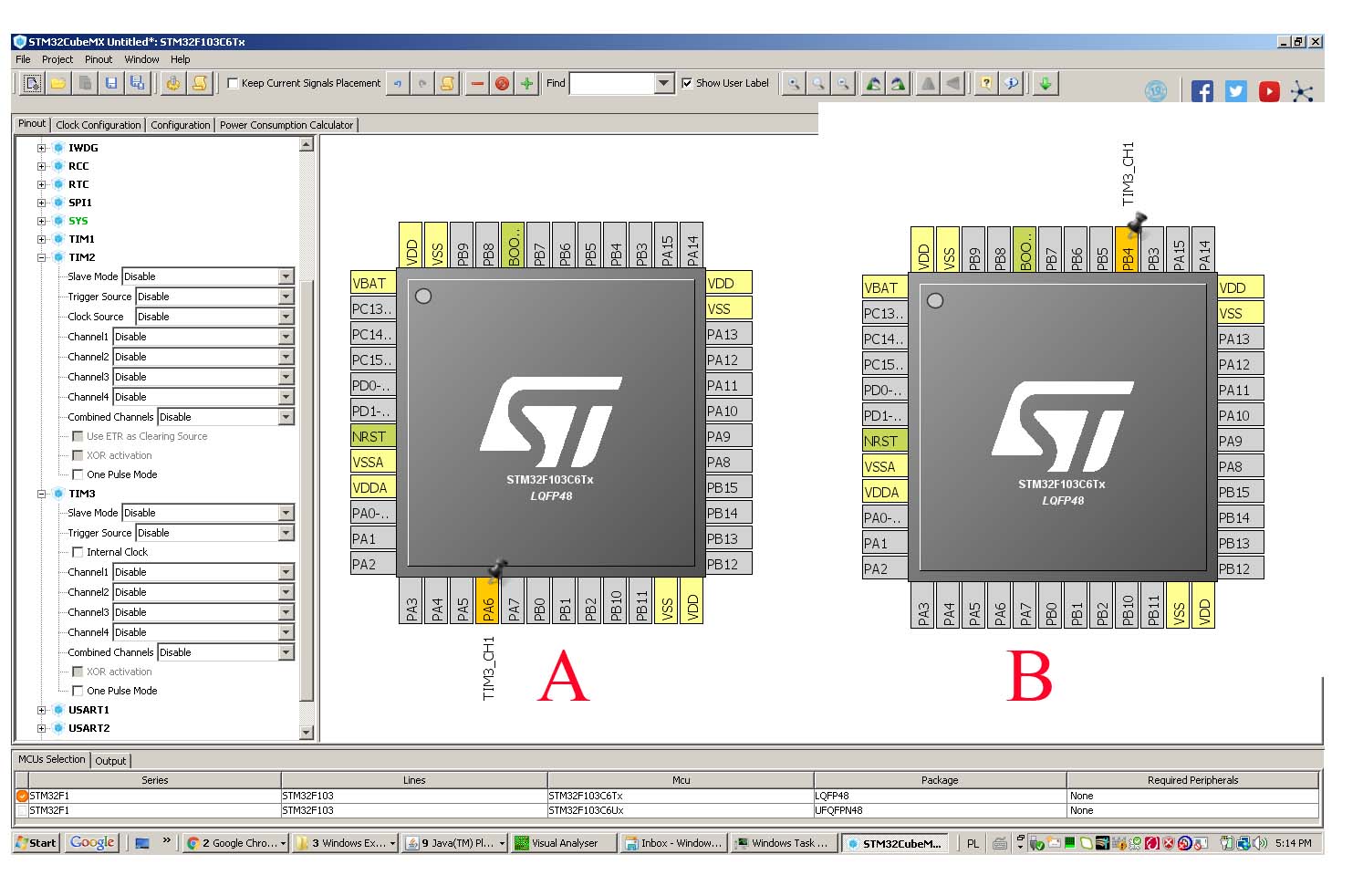
This is a simple generator for 1.5 MHz, I want to change output of it to PB4, both of them are PWM 3/1.
Generator is working ok for PA6 , for PB4 - is nothing on that pin.
Any solution ?

HardwareTimer pwmtimer3(3);
void setup() {

  pinMode(PA6, PWM);  // 1.5 MHz
  //pinMode(PB4, PWM);  // 1.5 MHz
  pwmtimer3.pause();
  pwmtimer3.setPrescaleFactor(1);
  pwmtimer3.setOverflow(48 - 1); 
  pwmtimer3.setCompare(TIMER_CH1, 24);
  pwmtimer3.refresh();
  pwmtimer3.resume();
}

So you are using the "BluePill" STM processor board. You will probably have to ask in their forums since that is not an Arduino board.

I don't know what the "PWM3/1" is supposed to mean. On other BluePill pinouts it is shown as "T3C1". They are different pins on different ports (B4 and A6) so maybe you have a choice of which pin to use. You will need to study the BluePill documentation to see if that is the case and how to select which pin is used.

I am here after visiting the link, may be the answer is there but I can't find it ?

http://www.st.com/content/ccc/resource/technical/document/datasheet/33/d4/6f/1d/df/0b/4c/6d/CD00161566.pdf/files/CD00161566.pdf/jcr:content/translations/en.CD00161566.pdf

STM32Cube it confirms post #1

johnwasser:
So you are using the "BluePill" STM processor board. You will probably have to ask in their forums since that is not an Arduino board.

I don't know what the "PWM3/1" is supposed to mean. On other BluePill pinouts it is shown as "T3C1".

Not arduino board but arduino IDE, STM forum is much less active than this one.

3= Timer number
1= channel number
Each timer has 4 channels

Problem solved