I am using the A4988 Stepper motor driver (purchased here) with a stepper motor (here), but I can't figure out how to use it!
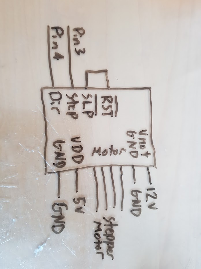
I have followed the instructions in the datasheet (here) and my wiring is shown in the attachments.
The code I am using is:
/*     Simple Stepper Motor Control Exaple Code
 *
 *  by Dejan Nedelkovski, www.HowToMechatronics.com
 *
 */
// defines pins numbers
const int stepPin = 3;
const int dirPin = 4;

void setup() {
  // Sets the two pins as Outputs
  pinMode(stepPin,OUTPUT);
  pinMode(dirPin,OUTPUT);
}
void loop() {
  digitalWrite(dirPin,HIGH); // Enables the motor to move in a particular direction
  // Makes 200 pulses for making one full cycle rotation
  for(int x = 0; x < 200; x++) {
    digitalWrite(stepPin,HIGH);
    delayMicroseconds(500);
    digitalWrite(stepPin,LOW);
    delayMicroseconds(500);
  }
  delay(1000); // One second delay

  digitalWrite(dirPin,LOW); //Changes the rotations direction
  // Makes 400 pulses for making two full cycle rotation
  for(int x = 0; x < 400; x++) {
    digitalWrite(stepPin,HIGH);
    delayMicroseconds(500);
    digitalWrite(stepPin,LOW);
    delayMicroseconds(500);
  }
  delay(1000);
}
I am using an ATX power supply, and a multimeter shows 12v and 5v where they should be, however, the motor does not move. The motor is not even held in position.
Does anyone have any experience with anything like this? any help would be appreciated
I put an A4988 on a breadboard and wired it according to the 20180129_150024.jpg photo with 12V power to the stepper and enable not connected. I loaded the code that you posted on my Uno. My motor runs forward and reverse in a loop like one would expect by the code. The code is OK. The driver wiring works (for me). Have you adjusted the coil current limit? This page explains how.
Do you have an Ohmmeter? Check the continuity of the motor coils to make sure that the coils are good and that the coil connections to the driver are proper ie 1a and 1b go to a coil and 2a and 2b go to a coil.
All the current limits have been set (my vref voltage is 0.2v)
I've got a few A4988 boards, and I've swapped a few of them into this circuit - without success.
The coils both have 35 ohms across them and the coils are connected as in your previous post. I also have a few motors, which have been swapped between.
The coil resistance of 35 Ohms is seems very high for a modern bipolar motor that the A4988 is made for. It should be on the order of 1/10 that resistance. The motor that I tested with is 3.0 Ohms.
irwinl11:
.The coils both have 35 ohms across them and the coils are connected as in your previous post. I also have a few motors, which have been swapped between.
I have some motors similar to those and they work fine with my A4988 drivers. The Pololu page has a good wiring diagram.
Is it possible you have damaged the drivers - it is very easy to do that if you disconnect the wires between the motor and the driver, even briefly.
This code may be trying to make the motors move too quckly
From what I can see, the circuit and code are probably correct and I've just blown my drivers. This is annoying but at least I can learn from this mistake, and anyone reading this thread will as well.
35 ohms means you will probably need at least an 18V supply to chopper-drive that motor as its
very high impedance.
Try turning the current down to 60% of its nominal value for the motor, you might then have enough
voltage headroom to run at only 12V supply.
Bipolar NEMA17 motors would normally be low impedance (1 to 3 ohms) for chopper drive, indeed these
low impedance motors are more common and cheaper, and low impedance motors can go a lot faster
at any given supply voltage when chopper driven.
These days you'd be wise to get a DRV8825 driver, not A4988, as its it can handle more current (or
run cooler, same thing).