hi guys , I have a problem with a honetwells transducers pressure sensor SPTMA0100PG5W02 ]
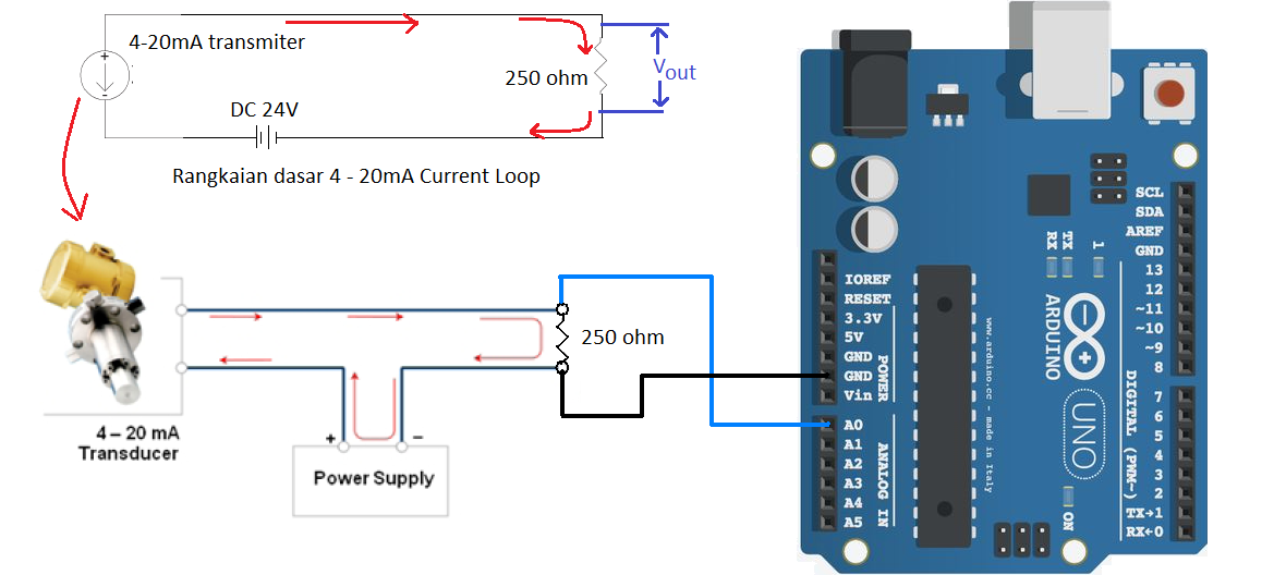
this sensor outpus is a 4-20ma, so I add a 250ohms resistance as a bridge on the negative to the sensor, checking amp on the sensor shows 4 to 20ma, but if I want to read the voltage it gives me a reading of 2.25v and does not change,
i alse try adding a 10k resistance before the analog signal, without luck and then a 100uf capasitor in parallel with the resistance of 250ohms, but in all cases the same thing happens,
Someone knows what my problem is, I dont know whats wrong with my circuit, thanks
right now im not using any sketch only multimeter , if i check the voltage crossing the 250ohm resistor gave me 2.24 volts to 2.25 , dont change , my power source is 12v 5amps if i check the amps it works for the voltage is static
You indicated that you are using a 12V power supply with a 250 ohm termination resistor (to convert the 4-20 mA to 1-5V). The specification sheet (page 2) for your sensor says that the recommended power supply voltage is between 12.5V and 24V. That voltage is what is required across the sensor terminals for the sensor to operate properly. Your power supply voltage has to be even higher yet since you will loose some voltage across the termination resistor. When there is 20mA flowing, 5 volts is lost across the 250 ohm resistor. This means that when using a 250 ohm resistor, you need 12.5V + 5V = 17.5V (at least) to power your sensor properly. You can use higher valued termination resistors and power supply voltages higher than 24 volts, but you must ensure that the voltage across the sensor never exceeds 24V.
There is a graph on page 4 of the spec sheet showing a range of termination resistors and power supply voltages, but be careful using it, you can't actually use 40V and a 1200 ohm resistor (as indicated by the graph) without severely limiting the range of operation; it will be far less than 4-20 mA. Lower valued resistors are preferred, but there is nothing wrong with the 250 ohms you chose if you have a 17.5V power supply. These sensors were designed to be used with industrial instrumentation equipment which is usually powered with 24VDC.
I strongly suggest that you NOT connect your sensor circuit to your Arduino board until you get it operating correctly; a mistake could easily blow up your Arduino board. Use a voltmeter to ensure you get 1-5V across the resistor before connecting to your Arduino board.
A secondary consideration is that you are using separate power supplies to power your sensor and your Arduino board. Putting a voltage on one of the Arduino pins when your Arduino board is not powered up can destroy the Arduino input pin. You must ensure that your Arduino is powered on first before powering your sensor, and you must turn off your sensor power before turning off your Arduino power.
Finally, the SPT mA sensor is a 2 terminal device, there is no third terminal to connect; the shield is not part of the circuit. There is a "ground" shown on the sensor schematic (page 4), but this is an internal reference point within the sensor, it does not connect to the shield. Be careful with the polarity of the 2 wires; IN+ goes to the positive power source, IN- goes to the resistor.
A higher supply voltage should get your sensor working.
It seems like your sensor is producing a constant 9 mA of current. As long as you don't change the pressure (you never said you do) that output should not change.
So far everything sounds like it's in perfect working order to me.
Now if the voltage you measure across the resistor does not change with changing pressure on the sensor (so you will have to apply pressure there, somehow), it's probably time for a new sensor.
By the way, a 47 Ohm resistor and using the internal 1.1V analog reference tends to give you a more stable signal for this kind of current loops.
Just to be clear. It is a 100 psi sensor. You have tested the sensor by measuring the current flowing through it when you apply the full pressure range and have measured between 4mA and 20mA. For this test you used a 12volt supply. Is that correct ?
By the way, a 47 Ohm resistor and using the internal 1.1V analog reference tends to give you a more stable signal for this kind of current loops.
Yes but the load line in the data sheet shows a minimum voltage of 12V with a resistor of 250R. In other words it can’t deliver the rated current into such a small resistor and still work correctly.
Supply the probe with 12v and put a mA meter in series.
The lowest mA value should be 4mA with no pressure on the probe.
Bad idea.
The resistance for the mA meter will be much lower than the minimum 250Ω required by the probe, effectively creating a short. That's a terrible idea, and a way to destroy the sensor there and then. You must have a resistor in series.
wvmarle:
Bad idea.
The resistance for the mA meter will be much lower than the minimum 250Ω required by the probe, effectively creating a short. That's a terrible idea, and a way to destroy the sensor there and then. You must have a resistor in series.
Wrong, its a constant current source output, so short-circuiting it is absolutely fine. (Just like
open-circuiting a voltage source is fine).
The short-circuit current is given as 18mA in the specifications even, so its clearly not going to damage
itself or an ammeter.