My overall goal:
I want to control some servo motors from an Android App which I've built. The mechanics of it are very simple, I'll press a button inside the app which should transmit the letter "a" to my Arduino board.
My problem:
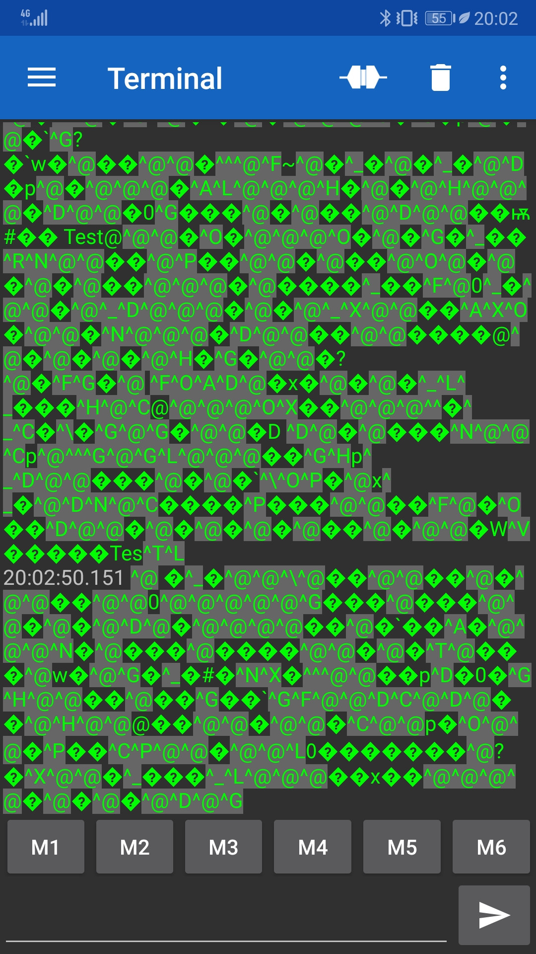
Doesn't matter if I'm trying with my app or with other Bluetooth Serial Terminal apps on the store, whenever I send the letter "a" from my phone to the Arduino board, I get either a reversed question mark or a multitude of random characters.
I've spent my whole day trying to figure it out and nothing came out of it.
The latest sketch I've tried should display the text "Bluetooth Test" on both my Bluetooth Serial app and also on my Serial Monitor. In the pictures below you'll notice that it says "Bluetooth Test" on the Serial Monitor, while in the app there are a bunch of random characters.
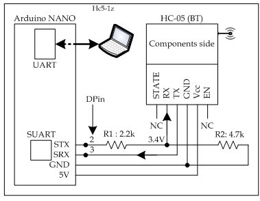
Connected the VCC of the module to my 5V rail, the GND to GND, TX to Digital 3, RX to Digital 2 trough a voltage divider.
Next, I will post a link to Imgur with pics of the Bluetooth Module, the board, a screenshot from my phone showing the weird characters, and a screenshot of my PC showing the code and also the Serial Monitor: Imgur: The magic of the Internet
TL;DR I want to send a character from a Bluetooth Serial Terminal app to my Arduino via the HC-05 and weird characters show up instead of the wanted character.
No it doesn't, and removing it is is a bad idea, indeed, the whole loop is 100% kosher. @gflu, you imply you are using external power for Bluetooth. You may have good reason for this, but Bluetooth will work OK off Arduino's 5v pin. Your problem is that you have Bluetooth wired wrong way round - Tx>Tx and Rx>Rx. i.e. the transmitter is connected to a transmitter which won't receive and a receiver can't get anything from the other receiver. Make sure you have Tx>Rx and Rx<Tx.
Nick_Pyner:
No it doesn't, and removing it is is a bad idea, indeed, the whole loop is 100% kosher. @gflu, you imply you are using external power for Bluetooth. You may have good reason for this, but Bluetooth will work OK off Arduino's 5v pin. Your problem is that you have Bluetooth wired wrong way round - Tx>Tx and Rx>Rx. i.e. the transmitter is connected to a transmitter which won't receive and a receiver can't get anything from the other receiver. Make sure you have Tx>Rx and Rx<Tx.
I have the external power because I need it in my project. This sketch is made just to test the Bluetooth connectivity.
I tried wiring the Rx and Tx both ways and it still transmits info back and forth, but on my phone it still receives random characters, exactly like in the screenshots attached in my first post.
Basically, what I'm trying to do is send the letter "a" from a Serial Terminal on my phone to my Arduino Board. With the letter successfully sent, I'll be able to control some servo motors.
gflu:
I tried wiring the Rx and Tx both ways and it still transmits info back and forth, but on my phone it still receives random characters, exactly like in the screenshots attached in my first post.
There is only one way round that will work. If you see it both ways, something else is going on. there is no image in your first post.
You might find the following background notes useful.
I put a link to imgur on my first post. There are 6 pictures uploaded. Front and back of my Bluetooth Module, how I wired the whole thing, and what's showing on my phone and on my computer.
I did put the Tx to Rx and Rx to Tx now that you've mentioned it. The pictures you're seeing on that link are from yesterday.
gflu:
Connected the VCC of the module to my 5V rail, the GND to GND, TX to Digital 3, RX to Digital 2 trough a voltage divider.
1. According to your above description, the connection that you have made between NANO and BT is depicted in Fig-1.
Figure-1:
2. Based on Fig-1, the object constructor code is:
SoftwareSerial BTserial(3, 2); // SRX | STX
And not the following which you have included in your sketch.
SoftwareSerial BTserial(2, 3); // RX | TX
3. Connect the PWM-pin of a Servo (SG-90) at DPin-5 and upload the following tested sketch. Send 'a' from your Android Phone and check that the Servo rotates by 450.
#include <Servo.h>
#include<SoftwareSerial.h>
SoftwareSerial SUART(3, 2); //SRX-pin of UNO connects TX of HC05
Servo myServo;

void setup()
{
  Serial.begin(9600);
  SUART.begin(9600);
  myServo.attach(5);
  myServo.write(0);  //0 position
}

void loop()
{
 byte n = SUART.available();
 if(n !=0)
 {
  char x = SUART.read();
  if(x == 'a')
  {
    myServo.write(45);
  }
 }
}
GolamMostafa: 1. According to your above description, the connection that you have made between NANO and BT is depicted in Fig-1.
Figure-1:
2. Based on Fig-1, the object constructor code is:
SoftwareSerial BTserial(3, 2); // SRX | STX
And not the following which you have included in your sketch.
SoftwareSerial BTserial(2, 3); // RX | TX
3. Connect the PWM-pin of a Servo (SG-90) at DPin-5 and upload the following tested sketch. Send 'a' from your Android Phone and check that the Servo rotates by 450.
#include <Servo.h>
#include<SoftwareSerial.h>
SoftwareSerial SUART(3, 2); //SRX-pin of UNO connects TX of HC05
Servo myServo;
void setup()
{
Serial.begin(9600);
SUART.begin(9600);
myServo.attach(5);
myServo.write(0); //0 position
}
Did exactly as you said and it doesn't move.
Made sure to properly wire the Bluetooth module as per your description.
I still get those weird characters on my Serial Terminal on my phone. You can see what I'm talking about in the fifth photo if you access the link: Imgur: The magic of the Internet
The image of the phone screen LOOKS like a mismatch of baud rate. If you have NOT been fiddling about with AT commands, it may be because HC-05 is set to a non-standard rate out of the box. I have heard rumour of this but I have never known if it was true. This might be the time, so you might try changing the software serial to different standard rates
38400
19200
115200
etc
And, while you are at it, you might check the howtos on inserting pictures, rather than relying on everybody to go trawling. The fact that you have got this rather proves the wiring is kosher and, apart from the baud rate, the same can be said for the code.
Make direct and single jumper connections between NANO and BT. Avoid the use of intermediate jumpers that cause problems. Use 5V of the NANO for the BT and not the external 5V. Have you uploaded my sketch of Post#9 that I have tested in my setup?
The image of the phone screen LOOKS like a mismatch of baud rate. If you have NOT been fiddling about with AT commands, it may be because HC-05 is set to a non-standard rate out of the box. I have heard rumour of this but I have never known if it was true. This might be the time, so you might try changing the software serial to different standard rates
38400
19200
115200
etc
And, while you are at it, you might check the howtos on inserting pictures, rather than relying on everybody to go trawling. The fact that you have got this rather proves the wiring is kosher and, apart from the baud rate, the same can be said for the code.
I thought about the fact that the module could be set on a different baud rate and I tried using the command AT+UART? in the serial monitor but it doesn't show anything at all, not even what I wrote.
Regarding the pictures, I did try to upload them directly onto my post but it wouldn't work with an Imgur URL. Which site should I use for uploading them?
The wiring is as follows: USB Inserted into Nano. Vcc of HC-05 inserted into 5v of nano. Gnd to Gnd of Nano. Tx into Rx. Rx into Tx through a voltage divider made out of one 1k resistor and one 2k2 resistor. On pin D5 I connected my Servo, as GolamMostafa suggested in post #8.
GolamMostafa:
Make direct and single jumper connections between NANO and BT. Avoid the use of intermediate jumpers that cause problems. Use 5V of the NANO for the BT and not the external 5V. Have you uploaded my sketch of Post#9 that I have tested in my setup?
So the wiring is as follows: USB Inserted into Nano. Vcc of HC-05 inserted into 5v of nano. Gnd to Gnd of Nano. Tx into Rx. Rx into Tx through a voltage divider made out of one 1k resistor and one 2k2 resistor. On pin D5 I connected my Servo. I did upload the code you provided on post #9 but as soon as I plug the servo into pin D5 it starts vibrating, without any movement of the "upper part".
So, check the functioning of the Servo first using the following tested sketch. There is no need of BT and Phone. Check that the Servo has come to zero position and then after 2-sec, it has gone to 60 degree position. There is no jitter/vibration.
GolamMostafa:
So, check the functioning of the Servo first using the following tested sketch. There is no need of BT and Phone. Check that the Servo has come to zero position and then after 2-sec, it has gone to 60 degree position. There is no jitter/vibration.
I connected the USB to the Nano, the servo to an external power source, and the signal cable to D5. It was really jittery. How I was able to solve the jitter was by connecting the + and - of the power supply to the Nano Vin and GND. Now it doesn't jitter at all and it moves from 0 to 60.
Update: with the Nano connected to my power supply, not only to the USB (which is connected on the front panel of my PC), the code in post #9 works. If I press the reset button on the Nano and then send the letter "a" from my Bluetooth Serial Terminal app, it moves to position 45, as it should.
Since it now works as it should, I think that the problem was that the Nano wasn't getting enough power from the Front Panel USB port that it was plugged into. As soon as I plugged my external power source (5v, 4A) into the Nano, it all started working properly.
cattledog:
Was there an issue with the baud rate causing the "garbage" on the phone, or was the issue solely the power supply?
So earlier in the day I tried running the sketch suggested to me in post #8 and you saw the result on the terminal. Nothing was working.
The baud rates were set ok, I believe. In the code, and also in the Serial monitor, they were set to 9600. I didn't mess with them.
With the same exact code, from post #8, but with the Arduino getting power from my power supply it worked. That's why I'm thinking that the supply was the problem. As soon as I wired the Bluetooth Module to get the power strictly from the Arduino and the Arduino was getting power trough the Vin and Gnd of the supply, everything worked fine.
Before wiring them this way, the Bluetooth Module was getting power directly from the power source and the Arduino was only getting power through the USB (which was connected on the front panel of my PC).