Problem with I2C, possibly bus contention?

Hello,

My latest project is a precision thermometer using a TMP117 sensor on a Sparkfun breakout board. Other components are an Arduino Pro-Micro (3.3v 8MHz) ,a small Winstar OLED display (WEA012832FLPP), two 10K pullup resistors, and a battery supply. The KiCad schematic is as below. All devices operate at 3.3v.

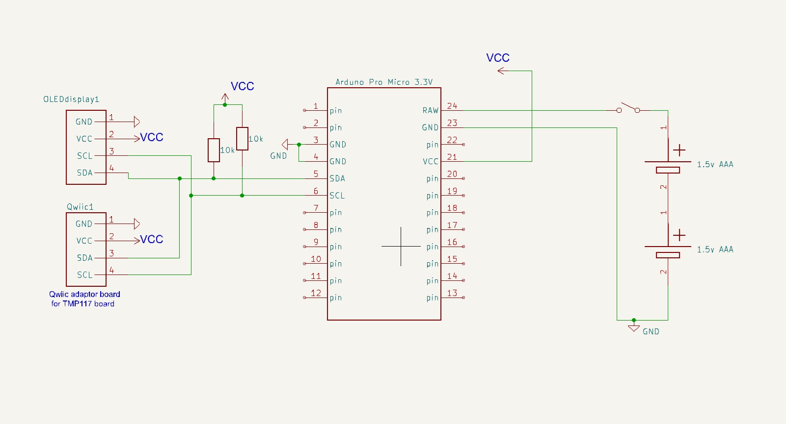
The TMP117 sensor address is 0x48, and the display SSD1306 address is 0x3C.

I have a problem with the I2C communication, which I think might be an issue of bus contention. I have written the following sketch to demonstrate the problem.

/* Test sketch to demonstrate I2C problem
   --------------------------------------
  With only the TMP117 temperature sensor connected -- works OK
     Temperature is printed in serial monitor
  With only the display module connected -- works OK
      Alternating "Hello", "Goodbye" are displayed.
  With both connected -- the display does not work
        Display is either frozen or garbled.

  TMP117 sensor address is    0x48
  Display SSD1306 address is  0x3C      
---------------------------------------------------------------*/
#include <Wire.h>             // Used to establish serial communication on the I2C bus
#include <SparkFun_TMP117.h>  // Used to send and recieve specific information from sensor
#include <SparkFun_TMP117_Registers.h>
#include <Adafruit_GFX.h>
#include <Adafruit_SSD1306.h>
#include <Fonts/FreeMonoBold12pt7b.h>
#include <Fonts/FreeMonoBold18pt7b.h>

#define SCREEN_WIDTH 128  // OLED display width, in pixels
#define SCREEN_HEIGHT 32  // OLED display height, in pixels
// Declaration for an SSD1306 display connected to I2C (SDA, SCL pins)
Adafruit_SSD1306 display(SCREEN_WIDTH, SCREEN_HEIGHT, &Wire, -1);
TMP117 sensor;  // Initalize sensor   The default address of the sensor is 0x48
bool flag = 1;
// -----------------------------------------------------------------------------
void setup() {
  //==========
  delay(4000);
  Wire.begin();
  Serial.begin(115200);   // Start serial communication
  Wire.setClock(400000);  // Set clock speed

  // // Display I2C address of display is 0x3C
  if (!display.begin(SSD1306_SWITCHCAPVCC, 0x3C)) Serial.println("SSD1306 allocation failed");
  // Above message not printed altho display is disconnected??

  // Check if the sensor will correctly self-identify
  if (sensor.begin() == true) Serial.println("Sensor Begin");
  else Serial.println("Sensor failed to setup");

  display.setFont(&FreeMonoBold12pt7b);
  display.setTextSize(1);
  display.setTextColor(WHITE);
}
// ------------------------------------------------------------------------
void loop() {
  //=========
  if (sensor.dataReady() == true) {
    float tempC = sensor.readTempC();
    Serial.println();
    Serial.print("Temperature in Celsius: ");
    Serial.println(tempC);

    display.clearDisplay();
    display.setCursor(20, 20);
      if (flag) display.print("Hello");
      else display.print("Goodbye");
    display.display();
    flag = !flag;  // Toggle

    // display.clearDisplay();
    // display.setCursor(0,20);
    // display.print(tempC);
    // display.print(" c");
    // display.display();

    delay(1000);
  }
  //delay(1000);
}  // End of loop
// =============================== End of File ==========================================

With only the TMP117 temperature sensor connected it works properly:
Temperature is printed in the serial monitor.

With only the display module connected it also works properly:
Alternating "Hello", "Goodbye" are displayed on the OLED.

But with both connected the display does not work:
Temperature is printed correctly in the serial monitor,
but the display is either frozen or garbled.

Above behaviour is the same whether power from USB or from batteries, except there is of course no serial monitor with batteries.

I've searched the forum, and am aware that there are many posts about I2C, but I havn't found anything that helps. I've also had a look at all the Wire library functions, but cannot fathom how to use them to maybe fix this problem.

Obviously, in the "real" project I will use the OLED to display the temperature, not "Hello", "Goodbye". That is just for this demo.

Can you help? Thank you, Ken.

Use an I2C scanner to find out which slaves are recognized. Try lower pullup resistors (2k2) for 3.3V supply..

You may be running out of memory. The display alone takes almost half of the Arduino Pro Micro RAM. Post the summary of memory use at the end of the compilation step (which won't show the 1K bytes consumed by the display allocation).

If you power your board from 3V battery to RAW (trough LDO), for sure devices don't operate at 3.3V.
Likely ~2.7V with new batteries. Which might be too low for some component of the setup.

Just off the top of my head:

On the information you have provided, there is enough to make me go hmm without going anywhere near some mysterious and undefined "I2C bus contention".

According to your schematic, on battery power you are feeding 3V into the RAW pin.

The RAW pin is the input to a 3.3V regulator.

Even an LDO regulator isn't going to output 3.3V when fed with 3V.

To rule out RAM shortages, use the F() macro in your prints. And to start with, use the default font. Simplify, simplify, simplify.

Oh, and I do hope you have never connected the USB when the battery is connected. There's no blocking diode on the RAW line to prevent backfeeding 5V into your 3V battery.

Hi, @kenarton

Did you write your code in stages, testing and debugging as you wrote?

If so you should have some code that just reads the sensors and puts the data on the IDE serial monitor.

If not, then write some code just to test sensor, and get it working.
THEN.
If not, then write some code just to test display, and get it working.
THEN combine them.

At what stage of your code writing did you notice this fault?

Did you test your sensor and display with example code from the libraries?

Tom.... :smiley: :+1: :coffee: :australia:

Just some other suggestions:

  1. Blink a the onboard led at the beginning of setup() to see if it is a crash cycle (say brownout).
  2. Move the line if (!display.begin(SSD1306_SWITCHCAPVCC, 0x3C)) Serial.println("SSD1306 allocation failed"); after the initialisation of the of the sensor because (at least) the display.begin() checks the available storage and fails if there is not enough.

Thank you for your replies and suggestions. I hope it is OK if I now reply to them all in a single post.

My comment about bus contention was speculation, and probably wrong.

Unfotunately I don't have an I2C scanner.
Tried 2.2k pullups, same as before. TMP117 datasheet recommends 10k to avoid
heating sffects, i.e. for max accuracy.

When I say "All devices operate at 3.3v", I mean that's their nominal spec.
With battery, all device VCC are 3.0v, checked with a DMM.
Spec for the WEA012832FLPP has VCC min = 2.8v, but I know from other tests that it will operate down to about 2.4v.
The TMP117 spec is VCC from 1.8 to 5.5v
The ATmega32U4, which is used in Arduino Pro-Micro, has spec VCC from 2.7 to 5.5v.

I have tried with a bench supply at 3.3v instead of battery, and output at the VCC pin is very close to 3.3v.

And I DO know not to connect battery and USB at the same time !!

I did indeed write my code in stages -- got the sensor working perfectly on its own, and then got the display working perfectly on its own. And as I said in initial post, the code above works perfectly with either sensor or display. The problem only appears when they are both plugged in at the same time.

Possible memory issues:

Before edits, Memory usage reported after compilation:
Sketch uses 20824 bytes (72%) of program storage space. Maximum is 28672 bytes.
Global variables use 603 bytes (23%) of dynamic memory, leaving 1957 bytes for local variables. Maximum is 2560 bytes.
And then after upload:
avrdude: 20824 bytes of flash written

I have tried print(F) macro -- it is OK in setup, but will not compile when in loop.
I have removed the included font.

Memory usage reported after compilation is now:
Sketch uses 18408 bytes (64%) of program storage space. Maximum is 28672 bytes.
Global variables use 541 bytes (21%) of dynamic memory, leaving 2019 bytes for local variables. Maximum is 2560 bytes.
And then after upload:
avrdude: 18408 bytes of flash written.

After all of above, the behaviour is as before.

So for the individual tests of the display and sensor which worked, you used exactly the same code without commenting anything out. All you did was disconnect the devices. Is that so ?

This does not look like a memory problem to me although it is so that the display library allocates memory dynamically which does not show in these statistics.

For a pro micro ATMEGA32U4 you should really wait after this statement for the serial connection to become ready: Serial.begin(115200); otherwise you may miss error messages as you have hinted in your code. Usual is to do something like while( !Serial && millis() < 8000 );

Yes, that is correct, I use exactly the same code, and just plug in the sensor and/or display: One at a time is OK, both together does not work.

My code has delay(4000) at beginning of setup, to give me time to start serial monitor.

True but the 3.3V regulator needs at least 4.3V to remain in regulation.
You won't get anywhere debugging until you first provide the correct input voltage.

Print a message after the Serial.begin() to see if it really is ready.

When powered from USB the input voltage is 4.5v aand VCC is 3.3

When powered from battery the input to pin RAW is 3.4v (the batteries are actually lithium equivalents of AAA, hence slightly > 3.0) and VCC is 3.3. It is an LDO regulator

I have added message as you suggest — it really is ready.

Doesn't matter won't, properly regulate unless input is 3.3V +1V.

hence slightly > 3.0

Only when brand new and never used. The nominal voltage is 1.5V

OK, I concede on the regulator voltage.

But nevertheless the problem remains when powered from USB.

What if you run your single device test and then plug in the other sensor as well? Will the mere presence of both sensors cause the problem?

I' not a big fan of the Adafruit libraries, they tend to be bloated, are dependent on other adafruit libraries and often interfere with other non-adafruit libraries. Adafruit has their own library for handling I2C and it often interferes with others.

I would try another library for the display.

1 Like

Then get it.

Also, did you try with
Wire.setClock(100000);

You may have a memory problem. If you only need text, these libraries from ladyAda might be a better solution.

#include "SSD1306Ascii.h"
#include "SSD1306AsciiAvrI2c.h"

Adafruit have a tutorial on using them. They led to my only success with SSD1306, but i don't know how they play with other libraries.
1 Like

If I understand correctly, when both I2C devices are connected, the TMP117 works, but the display does not. That would suggest that the TMP117 is somehow interfering with I2C traffic when it's supposed to be tristated. The TMP117 board appears to have jumpers on the bottom that let you assign a different address to it. That shouldn't matter, but might be worth trying.

Also, it would be interesting to see if removing all references to the TMP117 in the code, including even the include for the library, but leaving the TPM117 physically connected, would make any difference. If the display is still messed up, then it's possible the TMP117 just won't let go of the lines, which could be a bad copy. I can't find anything online suggesting this is a common problem.

A more interesting test would be replacing the TMP117 with another I2C device to see if the display is still messed up.