I'm using a PWM Signal for controller a thruster, but a I can't supply a motor direct with a PWM signal form arduino, my motor work with 12Vdc/4A. Sure I'm using a transistor for supply base from transistor, but it's my problema. A signal PWM varible between 0 - 5Vdc, sure when I put the signal on the transistor, I have in motor until the maximun 5 Vdc, when I need 12 vdc.
Can somebody help me with mais problem. If posivel send me a schematic from de solution.
guaruja:
I'm using the TIP122, not MOSFET. I'm sending the schematic for you give ideas. Thanks.
You need to move the T5 transistor to the bottom of the circuit so that it will provide 'low side' switching to your H-drive circuit. Wire the +12vdc directly to the collector leads of T1 and T2. Wire the T5 transistor collector lead to the PE point, wire the emitter to the ground. You will also need a wire from this ground point to the +12v supply's negative terminal and another wire from this point to a arduino ground pin. Also you need a series current limiting resistor between the T5 transistor base lead and the arduino output pin, 500ohm should be ok.
Circuits will never provide full +12V on motors :
when HIGH level on CCW or CC inputs it completely switch on only T3 and T4.
The same time T1 and T2 would supply only ~4V to motors. Shift voltage circuitry required,
or easy way, buy H bridge L298 / similar.
If you insert T5 in the ground line, as retrolefty suggest, it would solve only one part of a problem.
As T1 and T2 are also emitter followers, the same "limit power" problem will persist.
Your circuit is good for 5V power supply only. Is you need 12V you have to find another.
I provide two links above, you can google more with search pattern:
"H bridge motor driver schematic".
BTW, 6 transistors http://www.pyroelectro.com/tutorials/h_bridge_4_transistor/img/schematic.png
has no diodes at the output, has no protection against both inputs HIGH, and no separate PWM input. You can improve it :
attach 4 diodes as shown on http://ikalogic.com/h_bridge.php (D2, D3, D4, D5);
take care in software NEVER drive both inputs HIGH;
and find a software solution that would not require separate PWM input ( using two others inputs as PWM, when one stay LOW another would control speed in one direction and vice versa).
I understand your explication. Now I have some doubt about the connections between arduino output and driver input.
I understand what I should connect one arduino PWM output on input 1 and another arduino PWM output on input 2, and connect ground from arduino in the same point the ground from the power supply. When I'll varible the PWM signal I'll have control of the direction and a speed in the motor, It's no necessary i spend another output. And I should actuate one direction each time. Not necessary actuate one channel in HI and another in Low, corret?
And is it necessary use diodos, because a saw in the datasheet about the transistors TIP122, TIP 125 that both has a internal diodos in its circuits?
You recommend will I use the optic isolater in auduino PWM output, for protetion the arduino?
And I should actuate one direction each time. Not necessary actuate one channel in HI and another in Low, corret?
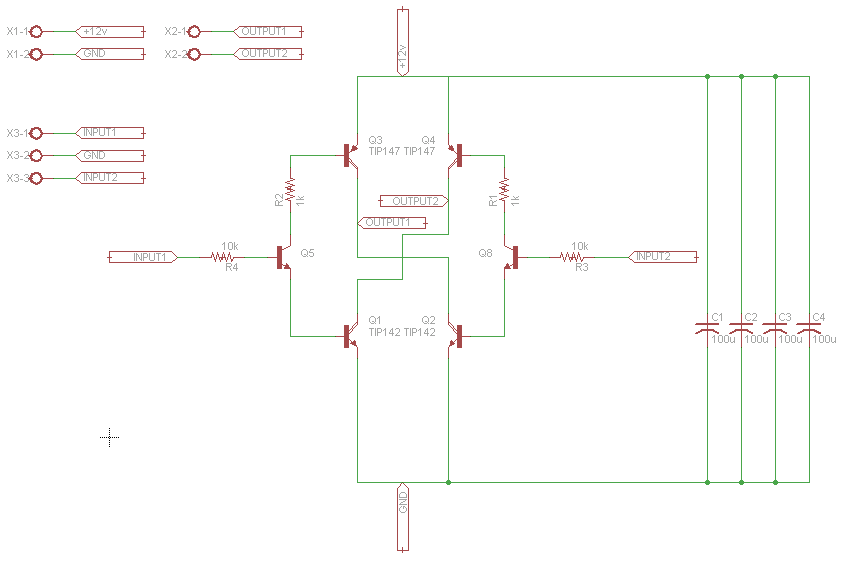
Yes, that's right. Two PWM pins A and B from arduino. Whenever A stay LOW, B provides PWM to control speed in one direction. If you decide to change direction, you set B to LOW, and regulate speed varying PWM A in another direction.
And you also right, TIP122 and TIP125 complementary Darlington with "build-in" diodes.
Q5 and Q8 could be any low signal / power NPN transistors.
edited:
TIP120 - 127
IC Collector Current (DC) 5 A
ICP Collector Current (Pulse) 8 A
You better stick with TIP140 - 147, as they more powerful
IC Collector Current (DC) 10 A
ICP Collector Current (Pulse) 20 A
Start up current for 4A motors could go up to 20A, may be more, you have to check on it.
Thanks for your help, the circuit worked perfectly. Now I would like lean how I do a communication RS232 between arduino and PC. I'm thinking to use a software develop in visual basic.
