The porpuse is to regulated the power supply from the arduino(with the help of DFR), and also measure voltage and current with the INA. Arduino communicates with INA and DFR via I2C interface.
Arduino, INA and DFR all share ground, and INA also needs to be connected to "power supply GND" to give good voltage readings. ...
The issue is that when I connect all the circuit, INA measures but DFR does not regulated, and if I disconnect the cable that connects "power supply GND" to INA, DFR regulates, but INA does not measure correctly.....
Probably the issue is coming from the fact that in the power supply documentation they specific tell you not to join the 0VDC from the control signal with the "power supply GND".
At the end I think I need to separate the GND of the DFR from the rest, but I don't know how.
I've tried to power the DFR with another 5V power supply, but it does not work (or at least the I2c interface doesn't communicate with the arduino...)
When INA is not connected to the "GND from the power supply", I can measure voltage with a multimeter and still DFR9071 regulates correctly, so I know it can be done..., of course the multimeter has his own "not share ground"...
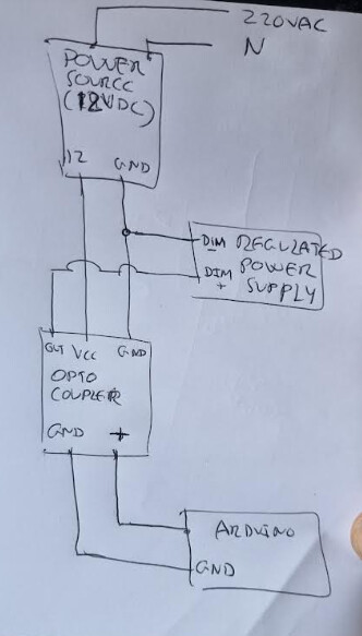
Better post the schematic of the whole circuit, including all modules.
I think that both INA and DFR have separated grounds for the load side and for the Arduino side, so it should work. But put the schematic, even hand drawn (better than Fritzing), otherwise is difficult to say anything.
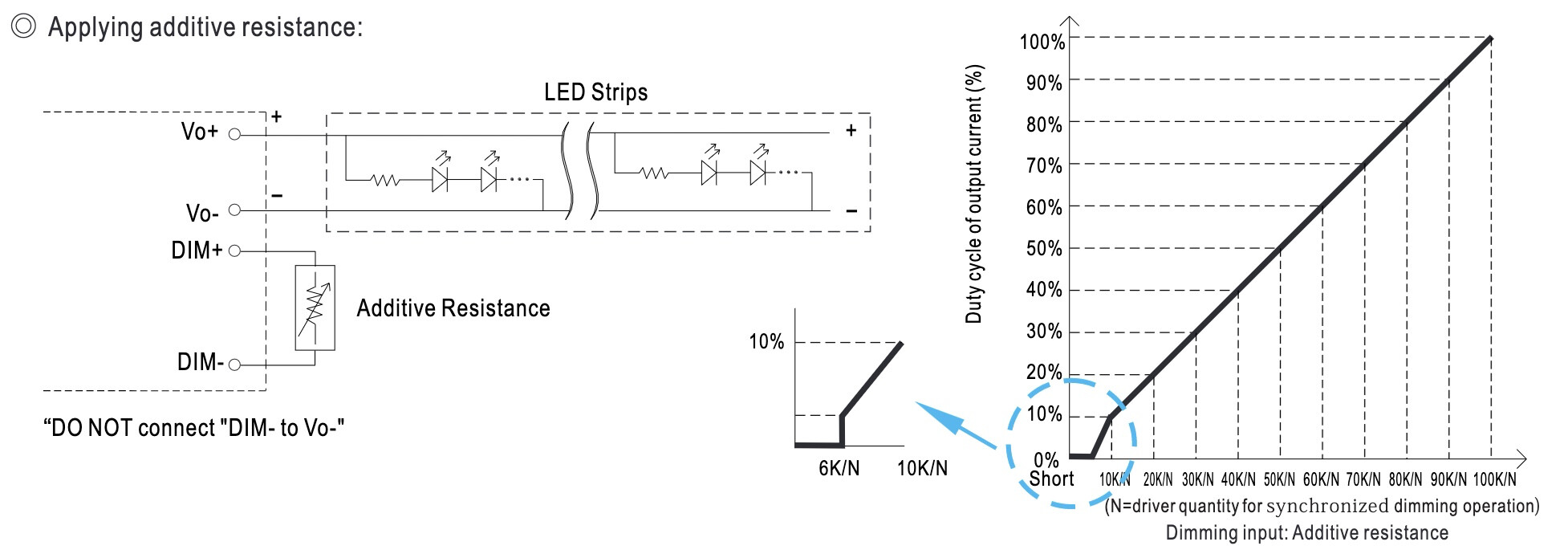
Use separate grounds for power and signal(voltage) reading. Large wire for power ground, any size for signal ground. Let them meet only at the ground of your power supply.
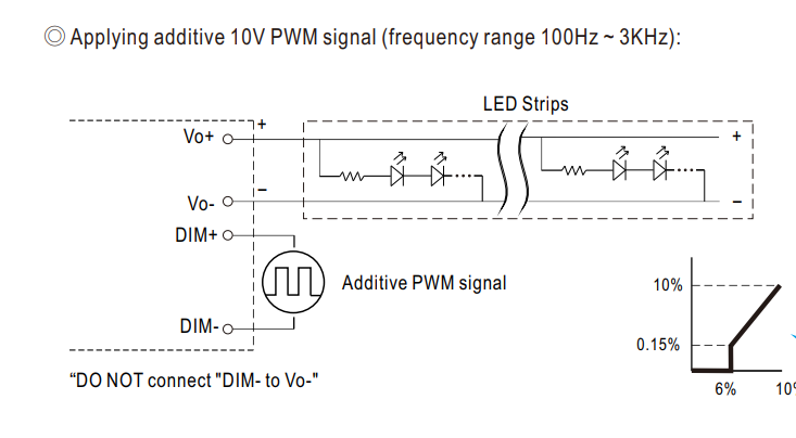
In the datasheet of the power supply it says: Do not connect DIM- with Vo-.
And... by the datasheet of the DFR it looks like both GND are connected:
So, it's connecting the DIM- and Vo- of the power supply
It's bad luck that the INA219 needs both grounds connected. Why can't it just read the relative voltage and encode in the I2C interface?
Anyway, I think that you have to think a way to get around this problem. Maybe a mosfet to connect it only for the reading. Or read the voltage in a different way.
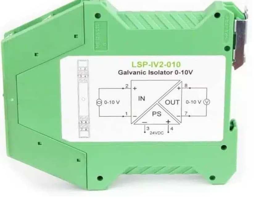
Maybe I can use one of this devices instead of the DFR, directly using the PWM 5V signal from the arduino to control de power supply.
(If I'm not wrong it's a 5V PWM converter to 0-10 Vdc, isolated):
From the image I can see what seems to be an optocoupler...I need an aditional power suppply, but I think GND is isolated from the PWM - input (DIN-), though I'm not 100% sure...
I think that Wava is right. You can use the PWM signal of the arduino and isolate it with an opto coupler,
taking into account that you need 10V to drive the power supply.
Maybe you could get the 10V from the power supply with an LDO.
-- Edit: not needed, see next comments.
Another option would be not reading the voltage with the INA219. What do you need it for? If you don't need precision you could try to calculate it from the current. If this is not linear enough, with a look-up table of 10 or 20 values. I don't know if this would be sufficient or could work in this case.
You don't even need that. When you leave the DIM pins unconnected, the supply is on, and when you short them, the light is off. What does that tell you.
Leo..
Ah, ok. So it works also just connecting and disconnecting the pins from each other, with the variable resistance mode, I see. I was thinking in feeding a 10V PWM, but it's not needed.
I have never used those regulated power supplies.
Yes, then is much simpler. Just an octo coupler and a resistor. The DFR is not needed.
@anon27210439, The project involves more elements, but I didn't want to complicate more for simplify porpuse.., I tried the table approach,, but as the consumption can have electrical motors running at different speeds with variable resistance... the voltaje can vary even with the same control signal from DRF...., that is why I need to measure the actual voltage.
@Wawa, What do you mean by "LED supply?, I don't know what you are refernig to...
When talking about an optocoupler are you talking about something like this?
This is arriving today, as the power supply can also be modulated with a 0-10VDC PWM signal, maybe instead of the DFR, I can use the optocoupler, that will convert a 0-5VDC PWM signal coming from an analog output of the arduino, to 0-12VDC PWM (isolated) that I can use to control the regulated power supply?... I'll try it today when it arrives, I think I will need a smalll 12VDC power supply, but does not an issue...
You don't need the 10V for anything, If I understand it right.
You can connect an PWM arduino pin to the octo coupler, and it directly across the DIM+, DIM- pins. This way:
With the Arduino PWM you will be switching from a resistance of 1KΩ and floating (very high).
Variable resistance is the third operation mode of the power supply:
But switching from full on to full off.
I have no experience with these devices, but this what I understand from the comments of Wawa and the datasheet.
3-With a variable resistance (0 to 1K). I tried with DS3502 from adafruit, but is 100K and it doesn't work.
In the 3 cases I need the optocoupler to separecte Dim- from "general control GND of the rest of the devices...". But as far as I understand, options 1 and 2 need and external power source, and the optocoupler doesn't give you that, that is why I think I need the aditional 12 VDc power source.
Yes, what I mean is the third option but NOT with a variable resistor.
The opto-coupler will work as a switch. If you connect it like in my schematic, across DIM+ and DIM-, it will quickly switch between only 2 resistance values: 1KΩ or infinite. You don't need to put any voltage there.
Then, the power supply will be switching quickly: ON and OFF, and with the Arduino PWM you regulate switching speed and therefor the power level.
I'm not sure if this will work, I think so. Maybe others have more experience with this and will comment also.
You can just try.
@anon27210439 you were absoluty right. With the optocoupler I bought, the power supply is perfectly regulated with the PWM signal coming from the arduino, no need for an extra 12 VDC power supply .
Sadly a new issue has arrise and I don't no how the hell happens. INA 219 measures the voltage badly when regulating the power supply,(it appears to go up and down in more or less a random way..) though when measure with a multimeter voltage goes up and down perfectly linear...., I'm going to try with an external voltage measure sensor and see what I get...
When the power supply reduces voltage, Motor reacts keeping current more or less constant, so at the end the power goes down progresivly when voltage goes down(and viceversa).