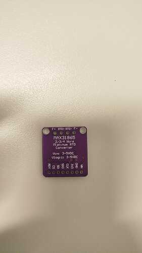
I'm doing an experiment in which I'm going to compare the readings in temperature of a LM35 sensor and and RTD Pt100 (2-wire), using the MAX31865. I connected the circuit as the image shows, using the analog pin A0 for the lm35, and the max31865 pins were connected as follows:
Vin -> 5V
GND -> GND
SCK -> D13
MISO -> D12
MOSI -> D11
CS -> D10
I'm using the following code to read the temperatures:
// Codigo para leitura do LM35 e PT100 com referencia interna de 1.1V
#include <Adafruit_MAX31865.h>

// Definicao dos pinos
#define LM35_PIN A0  // Pino do sensor LM35
#define MAX_CS 10     // Chip Select do MAX31865

// Inicializacao do objeto para leitura do PT100
Adafruit_MAX31865 max31865 = Adafruit_MAX31865(MAX_CS);

void setup() {
    Serial.begin(9600);  // Inicializa a comunicacao serial
    analogReference(INTERNAL);  // Define a referencia de tensao interna para 1.1V
    max31865.begin(MAX31865_2WIRE);  // Configura o MAX31865 para modo de 2 fios

    if (!max31865.begin(MAX31865_2WIRE)) {
      Serial.println("Erro na inicialização do MAX31865!");
      while (1); // Para o código se houver erro
}

}

void loop() {
    // Leitura do LM35
    int leituraLM35 = analogRead(LM35_PIN);
    float temperaturaLM35 = (leituraLM35 * 1.1 / 1023.0) * 100.0;  // Conversao para temperatura

    // Leitura do PT100
    float temperaturaPT100 = max31865.temperature(100.0, 430.0);

    uint16_t rtd = max31865.readRTD();
    Serial.print("RTD Raw: "); Serial.println(rtd);
    Serial.print("Status: "); Serial.println(max31865.readFault());

    if (max31865.readFault()) {
      Serial.println("Erro no RTD! Verifique conexões.");
      max31865.clearFault();  // Limpa o erro
}


    // Exibe os valores no monitor serial
    Serial.print("LM35: ");
    Serial.print(temperaturaLM35);
    Serial.print(" °C | PT100: ");
    Serial.print(temperaturaPT100);
    Serial.println(" °C");

    delay(1000);
}
When I run the code, the lm35 readings are great, but the RTD show only 988 degrees, or -242 degrees, the same 2 values in every reading. The "Raw" status show as "Zero" in the serial monitor.
Is there something wrong with the code? I tried to fix it in various ways, but the problem persists.
Also, what would be the correct way to connect the RTD in the max31865? I read that I should connect both wires in the RTD+ and RTD- of the module, and then make a short circuit between F- and RTD-. Is there something wrong with that project?
Thanks and advance for all the help!


