problems with my DIY sabertooth - arduino - segway

Hello!

I'm a teacher for physics and amongst others interested in robotics. Therefore I tried to build a segway based on the arduino and two sensors (gyro + accelerometer).

Two weeks ago I bought a sabertooth 2x60 motor controller von lipoly in germany. I use it for my DIY-segway. Here's the link to my building-thread: Segway - ein hoffentlich günstiger Versuch mit Arduino - Seite 4 - mosfetkiller-Forum
The sabertooth replaced my two fullbridges, which were controlled with PWM of the arduino. But the controller wasn't suitable to accelerate the motors enough, particularly when the segway was inclined quickly:

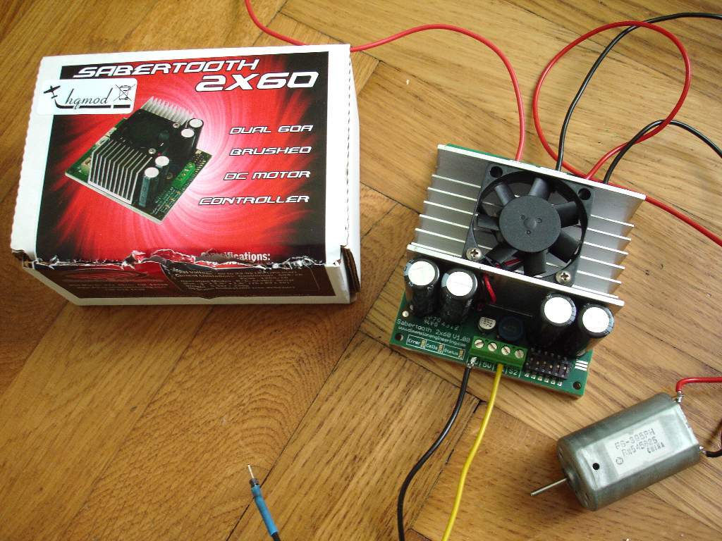
To get enough power and to avoid the annoying PWM-noise :wink: I bought the 2x60 controller.

The sabertooth-controller has several modes: analog, simple serial, advanced serial and RC. I'm using the simple serial mode with 9600 baud. I took the driver for the sabertooth-motor-controller directly from the dimensionengineering-homepage:

http://www.dimensionengineering.com/software/SabertoothSimplifiedArduinoLibrary/html/

Unfortunately I've now different problems:
If I test the sabertooth without my segway-program and the gyrometer/accelerometer, they perfectly do what they should. For example the start at 0, go full forward (+127), then down to 0 and to the opposite direction (-127).

If I test my gyro/acc without the sabertooth-controller, I get perfect values for the inclination and the motor-controller (between -127 and + 127). So both main parts do their work separately.
But when I start the arduino and the analog sensors (ADXL335 accelerometer and an analog gyro) and then I switch on the 24V for the sabertooth, the inclination-values go crazy and therefore the two motors too. The values vary very fast within -127 and +127 without any law, just by chance and arbitrarily :frowning:
Do you have any idea why the sabertooth interferes with the arduino-sensors? They have common ground over the arduino and I've changed the power-supply for the arduino three times. First with a separate 12V-batterieblock, second with one of the two 12V/12Ah lead battery and third with the 5V-Output of the sabertooth. The result was the same, the motors are going crazy.

Thank's for your efforts and support, a little bit frustrated Christoph from austria :wink:

How about posting the code? :stuck_out_tongue: I' pretty sure I already know why its not working properly. A look at the code can help. :stuck_out_tongue:

A wiring schematic showing the power supply and sabertooth setup would also be helpful.

Hello!

The code contains the important parts for a segway:

  • the part which determines the angle of slope based on the values from the gyro and accelerometer: I use a kalman-filter and as I mentioned before this part works perfect on its own.
  • the second part is the PID-controller for the motor-values: To find out the optimized values I use 3 potentiometers in a box for the coefficients of the P, I and D-part, fixed at the steerer.
  • the last part is to transfer the motor values to the motor controller: Using my DIY-fullbridges I sent the PWM-values from the arduino to an optokoppler of the fullbridge. Because of the low PWM-frequency of the Arduino (around 400 Hz), the noise was very annoying and the motor was not sensitive enough especially for low PWM-values. As you can see in the video, the segway was very unstable.
    Therefore I bought the sabertooth-controller, which can be driven with analog/simple serial/RC-Signals. At the moment I use the simple-serial-method.

I've contacted sabertooth too and they said, that I shouldn't use the driver with the Tx-pin for the communication between arduino and sabertooth. Instead of this I should try another pin (f.e. pin 12) for the Tx-communication. I'll try that at the weekend.

When I try the following code on its own it works and the two motors do what they should do.

// Copyright (c) 2012 Dimension Engineering LLC
// See license.txt for license details.

#include <SabertoothSimplified.h>

SabertoothSimplified ST; // We'll name the Sabertooth object ST.
// For how to configure the Sabertooth, see the DIP Switch Wizard for
// Sabertooth 2X25, 2X12 and 2X5 DIP switch configuration wizard
// Be sure to select Simplified Serial Mode for use with this library.
// This sample uses a baud rate of 9600.
//
// Connections to make:
// Arduino TX->1 -> Sabertooth S1
// Arduino GND -> Sabertooth 0V
// Arduino VIN -> Sabertooth 5V (OPTIONAL, if you want the Sabertooth to power the Arduino)
//
// If you want to use a pin other than TX->1, see the SoftwareSerial example.

void setup()
{
SabertoothTXPinSerial.begin(9600); // This is the baud rate you chose with the DIP switches.

ST.motor(1, 0);
ST.motor(2, 0);
}

void loop()
{
int power;

// Ramp motor 1 and motor 2 from -127 to 127 (full reverse to full forward),
// waiting 20 ms (1/50th of a second) per value.
for (power = -127; power <= 127; power ++)
{
ST.motor(1, power);
ST.motor(2, power);
delay(20);
}

// Now go back the way we came.
for (power = 127; power >= -127; power --)
{
ST.motor(1, power);
ST.motor(2, power);
delay(20);
}
}

But if I read the slooping angle to control the motor, the values go crazy. There is a kind of disruption and I believe because of the common ground of the arduino and the sabertooth. But the only way to seperate them electrically is using an optokoppler like I used for my fullbridges.
I've to mention, that the minus pole of the sabertooth-batterie-input (B-) is internally connected with the 0V-input on the other side of the controller. So the Arduino-GND is directly connected with the minus pole of the lead-batteries.

The use of the "simple serial" might not have fine enough control to prevent the apparent control overshoot/instability in some conditions. I think this control method uses a single byte to transfer the control info to the sabertooth. What component signal is unstable/hunting in the graph?

Thank's for your help. Today I tried to connect the sabertooth to an other pin for communication (pin 11 instead of Tx). I don't want to decry but it seems to work.

Before I checked this I found out, that just the Motor_1-output doesn't work. When I disconnect the Motor_1, the second motor works. Looking at the serial monitor of the arduino-program I could see two mysterious characters at the beginning of each line. Maybe this is a sign for a disturbed connection too.

But now with the changed pin the motors work and the two characters have disappeared. If the segway will now follow my commands I'll post the result on youtube and here at the forum.

Cheers, stoppi

Recent discussion you might find interesting.

http://forum.arduino.cc/index.php?topic=167618.0

I had always assumed that a Segway was ridiculously complex so it's great to see they can be controlled by an Arduino.

@stoppi_71 Would you be prepared to say how much it has cost?

...R

Thank's zoomkat for that interesting link :wink:

Building a segway isn't so complicated as you might think Robin. Concerning the costs it's always the same: When you know which parts work it's going cheaper. I've spent about 50 Euro in my not working fullbridges and another 40 Euro in the destroyed sensors. So i think that it's more economical to spend the money in working parts right at the start :stuck_out_tongue:

Until now I've spent more than 600 Euro for the segway but removing the "wrong paths" it'll be "just" 500 Euro. You won't build a segway much cheaper though there are articles in the internet which call rates in the amount of 300 Dollar. Here's a list of the main parts of my segway:

  • sabertooth controller 2x60 ..... 167 Euro
  • two complete 12" wheelset ...... 53 Euro
  • chain rings .......................... 18 Euro
  • chain with links .................... 28 Euro
  • two 24V/250W motors ............ 62 Euro
  • two lead batteries 12Ah .......... 20 Euro
  • batterie charger ................... 25 Euro
  • analog gyro ......................... 23 Euro
  • analog accelerometer ............ 12 Euro
  • .... mechanical parts, cable ....

At one time I thought about making a "faux" Segway by keeping the center of balance below the centerline of the wheel axels, somewhat like the below two wheeled routerbot test setup.

Thanks @stoppi_71

It sounds tempting.

I was allowed a go on a real one a few years ago - it was fun.

...R

It's going better and better but I've to replace my 250W-motors with more powerfull types (two 24V/500W).

I don't understand. I don't even know what language it is.

Also you are reopening a very old Thread - you may find it more useful to start a new Topic.

...R

hi yes but how do I do it along I've tried but it will slætte megdetsamme can then hjelp me where it's going
greeting ole