I am trying to build the op amp circuit from this paper here (go to Fig. 3). All the components I have are same as stated in the paper. However, I am having problems.
The DC offset is very high.
The photodiode is not very sensitive.
I want the output to go from 0 to 1023 (or 0 to 5V), and to my understanding, the op-amp is not giving the sensitivity it is supposed to.
When I add the input voltage of 5V to the pin 7 of the OP07 op-amp (datasheet here), the baseline jumps to ~900 or so. The photodiode (called FDS100) still reacts to light, but does not show large changes in the counts (between 0 and 1023).
I am wondering if the op-amp is shot. But I am not sure. I have attached an image of the breadboard circuit and the schematics (from the paper) I am following. Any thoughts?
Code:
int analogPin = A1;
int val = 0;

void setup() {
  Serial.begin(9600);
  Serial.println();
}

void loop() {
  int pinRead0 = analogRead(analogPin);
  float pVolt0 = pinRead0;
  Serial.print(pVolt0);
  Serial.println();
  delay(100);
}
Very special PCB techniques are required to handle 5 Gohm resistors and op amp circuitry at those low currents. That will never work on a breadboard.
The circuit requires a scrupulously clean and carefully designed PCB with guard trace isolation around the op amp inputs, and extremely clean, isolated ceramic supports for connections between the feedback resistor, the bias offset resistor, the op amp inputs and the photodiode.
A single fingerprint can have resistance of a few Megohms.
The circuit is incomplete because it does not show the power supply connections. The OP07 is specified to work with bipolar power supplies, +/- 3 V to +/- 18 V.
Finally, the blue component shown below (presumably a resistor) is not even in the circuit. The breadboard track is a short circuit between the terminals.
The 5 GOhm resistor near ground can be omitted. Never seen that level of amplification, there is something off. The photodiode can be biased for enhanced sensitivity.
There is a problem with the experimental set-up of the paper. The blue diode must be focused also with a lens, and the collector lens must be focused to where the blue light is incident. That way you'll increase much more your incoming light.
Try getting a chopper and lock-in amplifier.
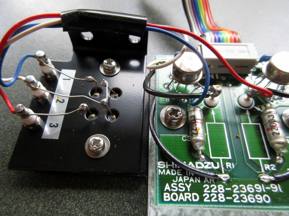
Here is an example of a commercial dual photodiode amplifier, taken from a Shimadzu spectrophotometer. R1 and R2 are 1 Gohm, on a separate PCB. The dual photodiode is mounted on a separate frame (image left). Note the teflon supports for the op amp input and photodiode connections.
It is fine as pictured, except that the schematic is incomplete, and a bipolar power supply is assumed.
This circuit shows the expected (albeit vastly reduced) gain of 2x10^6 V/A (op amp output in the simulation is 20 mV). But as mentioned, the 5 Gohm resistor circuit will never work on a breadboard. Totally impractical for beginners.
That would give the A/D value.
Try float pVolt0 = pinRead0 * 5.0 / 1024;
Build quality of that circuit is very important, because of the very high impedances involved.
Must have a bypass cap on the VCC pin. Can't be build on a breadboard or common circuit board.
10pF cap must be extreme low leakage (could be two short wires twisted together).
Everything must be shielded/grounded.
Post a picture.
Leo..
Another point, OP07 is not for this kind of job because it has a 'high' offset current, that's the reason of the high offset it is being measured. You need a difet op amp.
If you invert the sense of the photodiode you can get a positive instead of a negative voltage.
What is the basis for that statement? The spec sheet says typically 0.5 nA, comparable to the dark current of the photodiode, so that does not pose a major problem. The unusually large resistors do, though.
That means you can't just connect it to an Arduino input.
Add a 10k resistor between opamp output and Arduino pin, to reduce fault current to <0.5mA when the opamp swings negative. An optional Schottky diode between Arduino pin and ground, cathode to pin, could further protect.
Leo.
I would reinforce Jremington's advice.
It is a fiddle to deal with high impedances and low currents. A read of "keithley low level measurements handbook" is advised. It is a free download from them.
Someone here mentioned low leakage capacitors, I have used polystyrene in the past as they are very low leakage and lowish cost. I never found them in surface mount though, but that was some years ago.
Let us know how yo get on.
Thanks for your thoughtful comments. Maybe I am misunderstanding, but this measurement requires the LED and PD to be a 90 degree angle with another. The fluorescence light that is being detected is very weak, so yes the lens is needed to improve the signal.