I'm doing my 1st experiences with op-amps in a breadboard.
A lot of schematics that I found on line asks for +9/-9 or +12/-12 Volts.
I'm generating my signals with an Arduino Nano, so I have a 5V breadboard power-supply,
I'm producing +12V from that power supply using this boost converter: 1pcs 2A booster board DC-DC step-up input 2/24V to 5/9/12 / 28V Replace XL6009 | eBay
I found out that the standard way of getting +9/-9 V on a breadboard is using two 9V batteries connected in series, negative from bat 1 to positive of bat 2,
And a 220uF cap between the each rail and this GND.
My question is, can I do the same using 2 of those boost converters instead of the batteries ?
If yes, another question, that GND can be connected to the breadboard GND or should only be used on the GND pin of the opamps ?
Thanks in advance, sorry if the question is too stupid...
You can't do it with the usual boost converters because they're not isolated, and aren't inverting. The negative side of the output is tied to the negative side of the input - so if you connected the + of one to the - of another, you'd short the output. There are dc-dc converter topologies that will let you generate negative voltages - but the boost converter isn't one of them.
The dual-output supply mentioned above is an excellent way to get +/- 12v.
Ok, I was afraid of something like that, in my ignorance I decided not to try. Thank you DrAzzy.
In order to get the +-12V from the 5V I think I'll need a step up and not a step down, possibly something like this one.
Oh. ok. Then I'll probably better go to the 2 9v bats for the time being.
Do I need to add a 7809 and a 7909 ?
And about that GND, it should only be connected to the opamp GND pin ?
Oh. OK, I'm connecting VCC- to GND because I'm using them just with positive voltage.
The ones I got are uA741, I asked the guy at the electronics shop for some generics, good to run some tests. I have no idea if they are any good.
So far I can only say that they are working, but until I got an oscilloscope I wont learn much.
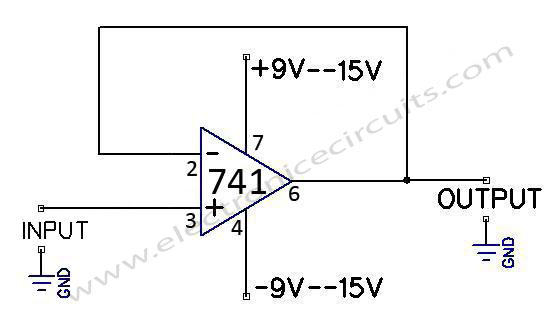
yes, that's a non-inverting buffer, right?
I have one of those just after my R2R dac, the only difference is that I'm connecting pin 4 to GND and pin 7 to +12.
You don't need exact +/- 12V for experimenting. +5V from Arduino and -9V from battery may be enough. Or +14 from Arduino+battery. But you can easily damage Arduino with such voltages! It is mostly good idea connecting pins of Arduino via 1k (or 10k) resistors to protect it a bit.
Maybe you can look for "rail-to-rail" output opamps. Powered from 5V, nearly safe, no problem with supply.
EDIT: I like LM2904: cheap dual opamp with supply voltage 3 to 30V, with inputs and output from GND (Vcc-) to 1.5 V under Vcc+. But I am no analog pro. Maybe there are better opamps.
ocsav:
I know that there are specialized power supplies with + and - outputs, but I happen to have 2 of those boost converters.
No, unlikely, you will have the standard cheap boost converters which are not isolated so
they share ground with the incoming power.
A lot of the circuits you will see with split-supplies are old designs from when opamps needed at
least 10V (ie +/-5V). Modern opamps include a whole bunch of good performers that run
at 3 to 5V and are rail-to-rail input and output, and older split-rail circuits can be adapted
using a 2.5V virtual ground.
Incidentally your +/-9V battery supply is going to be fine for almost any circuit designed for +/-15V
so long as you reduce the maximum signal amplitude to fit the available opamp input/output voltage
range. This is how most music effects-pedals are designed for instance (some are single 9V with
a 4.5V virtual ground).
For audio use switching regulators may be too noisy, and the battery version work better, BTW.