Hi everyone,
Recently, I tried to setup a new test for a beginner like me by connect and upload the code to ESP8266 -01 like people show me:
#include <ESP8266WiFi.h>
const char* ssid = "YOUR_SSID";//type your ssid
const char* password = "YOUR_PASSWORD";//type your passwordint ledPin = 2; // GPIO2 of ESP8266
WiFiServer server(80);//Service Portvoid setup() {
Serial.begin(115200);
delay(10);pinMode(ledPin, OUTPUT);
digitalWrite(ledPin, LOW);// Connect to WiFi network
Serial.println();
Serial.println();
Serial.print("Connecting to ");
Serial.println(ssid);WiFi.begin(ssid, password);
while (WiFi.status() != WL_CONNECTED) {
delay(500);
Serial.print(".");
}
Serial.println("");
Serial.println("WiFi connected");// Start the server
server.begin();
Serial.println("Server started");// Print the IP address
Serial.print("Use this URL to connect: ");
Serial.print("http://");
Serial.print(WiFi.localIP());
Serial.println("/");
}void loop() {
// Check if a client has connected
WiFiClient client = server.available();
if (!client) {
return;
}// Wait until the client sends some data
Serial.println("new client");
while(!client.available()){
delay(1);
}// Read the first line of the request
String request = client.readStringUntil('\r');
Serial.println(request);
client.flush();// Match the request
int value = LOW;
if (request.indexOf("/LED=ON") != -1) {
digitalWrite(ledPin, HIGH);
value = HIGH;
}
if (request.indexOf("/LED=OFF") != -1){
digitalWrite(ledPin, LOW);
value = LOW;
}//Set ledPin according to the request
//digitalWrite(ledPin, value);// Return the response
client.println("HTTP/1.1 200 OK");
client.println("Content-Type: text/html");
client.println(""); // do not forget this one
client.println("");
client.println("");client.print("Led pin is now: ");
if(value == HIGH) {
client.print("On");
} else {
client.print("Off");
}
client.println("");
client.println("Click <a href="/LED=ON">here turn the LED on pin 2 ON
");
client.println("Click <a href="/LED=OFF">here turn the LED on pin 2 OFF
");
client.println("");delay(1);
Serial.println("Client disconnected");
Serial.println("");
}
I put on the SSID, Password and I connect to the Wifi server and everything is seem to be alright. I got button to press ON and OFF but ...
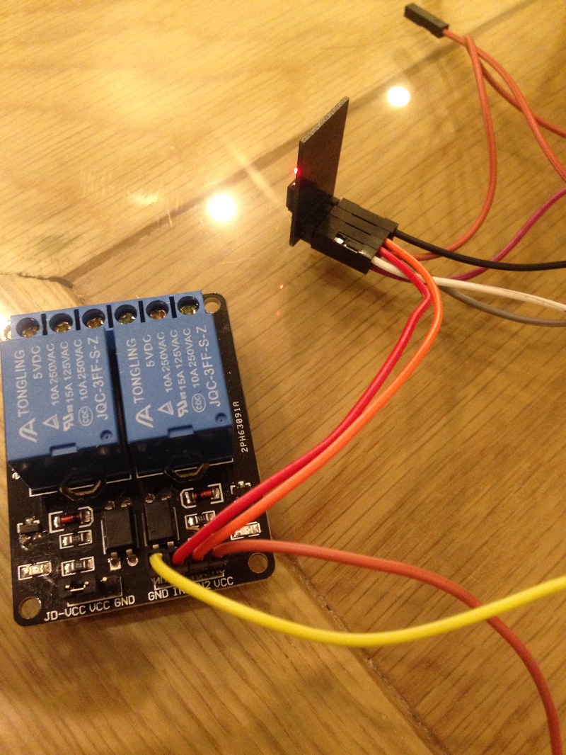
I connected the 2 GPIO of the ESP8266-01 to the Relay but nothing happen to the Relay when I press button on the web.
What did I miss? I attached Picture that I connect the Pin
Thanks for helping. I desperate working on it ![]()