Hi, I'm trying to program a DS2502 eeprom as per the instructions here:
In order to do so, there's a programmer to be made with a couple of transistors and resistors and so far I've had no luck getting in to work on a breadboard.
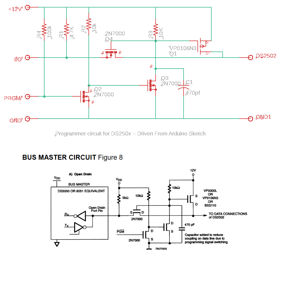
I'm wondering if the schematic on the github page is correct, it's the upper one on the image below. It seems to me that both arduino pins (I/O and PRGRM) would get +12V in this schematic which would likely damage my arduino. Looking at the datasheet of the DS2502 (extract on the bottom part of the included image) they do differentiate between 12V and VDD. This seems more logical to me. Should VDD just be the 5V on my arduino?
Thanks a lot for your insights,
Jens