You really should get one, a cheap one would be about 20. That's £20 or $20 or €20, maybe even less. Even a cheap one will help you a lot.
Very good. After checking the software... focus on the button... and is it making an unwanted connection... but only do one thing at a time, so this part can wait.
I don't think it's making an unwanted connection.
If I put an LED right in front of the button it lights up and then turns off when I press the button.
I am not certain of where the LED was placed, but you verified the button does something (we have not verified that it is placed correctly).
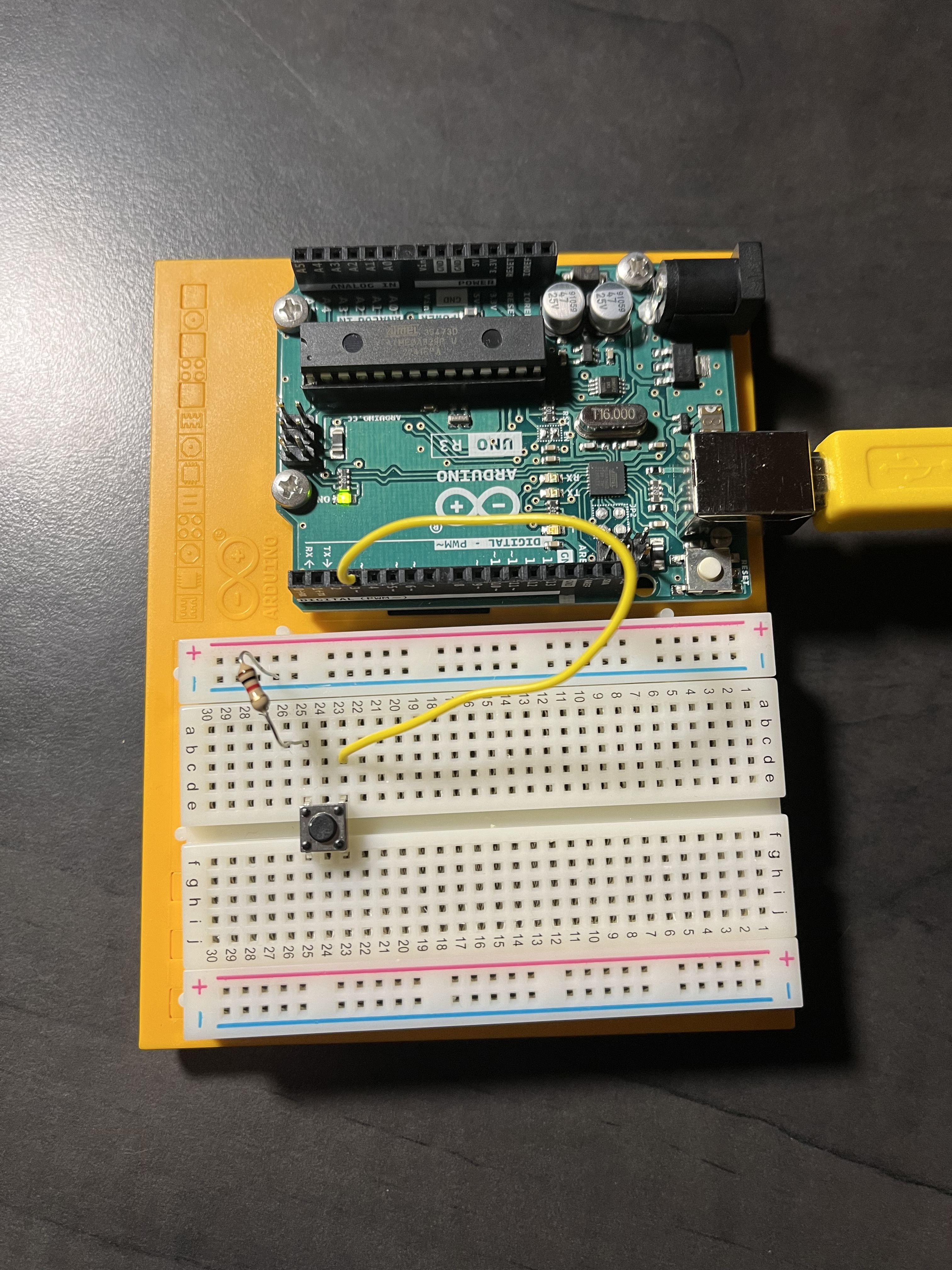
"Normal" all the connections (make the connections look as the diagram).
Test the Vcc rail by moving the red wire from the Vcc rail to row 23, between the green wire and the button leg.
I did that, nothing changed.
Does this mean "no LEDs light after the sketch is uploaded?"
Would you show (drawing, picture) how you connected the LED to the button in post #24?
Yes
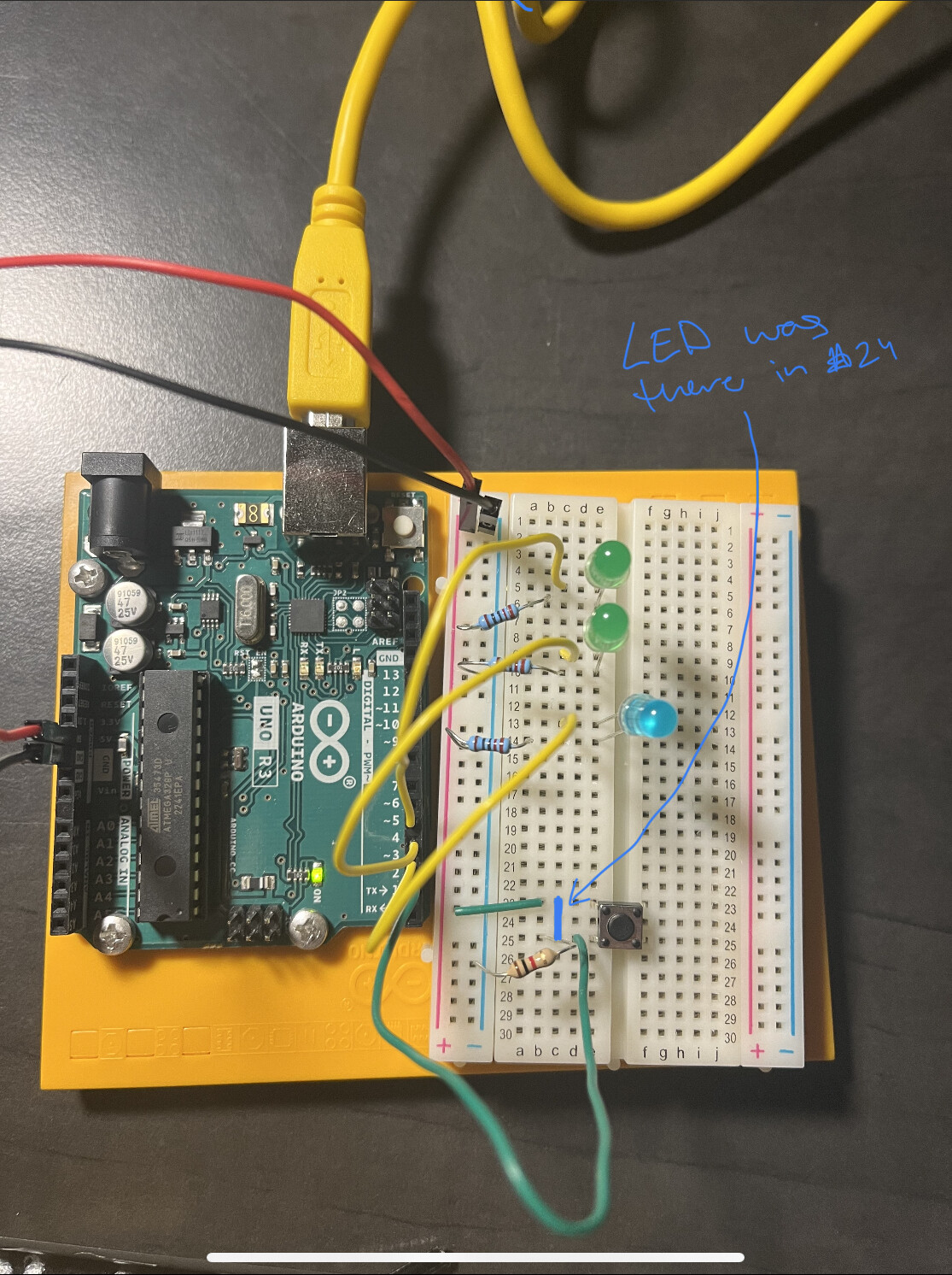
With the LED bridging rows 23 and 25, and forward biased, shows the power and ground paths were good to the button. The LED turning off meant the potential difference of + to - was zero, so no forward bias, and no lighting (meaning: the button press worked).
With your project connections "normal"... copy this code, verify and upload it... press the button, and look at the Serial Monitor... what do you see?
byte buttonPin = 2;

void setup() {
  Serial.begin(9600);
  pinMode(buttonPin, INPUT);
}

void loop() {
  Serial.print(digitalRead(buttonPin));
  delay(100);
}
I don't really understand this or know what I'm looking for but here's what I did. What button am I supposed to press?

After you upload your sketch (the -> arrow), You will see the Serial Monitor (bottom part of screen) become active. You should then press the button on your breadboard. While holding the button, look at the Serial Monitor again. What did you see before the button press, and during the button press, and after the button press.
I didn't see anything during any of the stages.
Before moving to the next step, look at this simulation... it shows how your Serial Monitor should have looked (see the 0 zeroes, then press a button to see the 1 ones... et cetera)
(Press the GREEN button with the WHITE arrow to start the simulation)
the code
//**************************************************
// - Connect a jumper wire to GND
// - Upload this sketch
// - Touch the jumper wire to pins 2 through 12
// - The output will show the pin you touched
//**************************************************

int buttonPin[] = { 2, 3, 4, 5, 6, 7, 8, 9, 10, 11, 12 };

void setup() {
  Serial.begin(9600);
  Serial.println("\nHello, World!");

  int h = sizeof(buttonPin) / sizeof(buttonPin[0]);
  for (int i = 0; i < h; i++) {
    pinMode(buttonPin[i], INPUT_PULLUP);
  }
}

void loop() {
  int h = sizeof(buttonPin) / sizeof(buttonPin[0]);
  for (int i = 0; i < h; i++) {
    int j = digitalRead(buttonPin[i]);
    if (!j) {
      Serial.print(buttonPin[i]);
      Serial.print(":");
      Serial.print(j);
      Serial.println();
      delay(1000); // allow time to remove the jumper
    }
  }
}
diagram.json
{
  "version": 1,
  "author": "Anonymous maker",
  "editor": "wokwi",
  "parts": [
    { "type": "wokwi-arduino-nano", "id": "nano", "top": 0, "left": 0, "attrs": {} },
    {
      "type": "wokwi-pushbutton",
      "id": "btn1",
      "top": -51.4,
      "left": 134.4,
      "attrs": { "color": "green" }
    },
    {
      "type": "wokwi-pushbutton",
      "id": "btn2",
      "top": -99.4,
      "left": 134.4,
      "attrs": { "color": "green" }
    },
    {
      "type": "wokwi-pushbutton",
      "id": "btn3",
      "top": -147.4,
      "left": 134.4,
      "attrs": { "color": "green" }
    },
    {
      "type": "wokwi-pushbutton",
      "id": "btn4",
      "top": -195.4,
      "left": 134.4,
      "attrs": { "color": "green" }
    },
    {
      "type": "wokwi-pushbutton",
      "id": "btn5",
      "top": -243.4,
      "left": 134.4,
      "attrs": { "color": "green" }
    },
    {
      "type": "wokwi-pushbutton",
      "id": "btn6",
      "top": -291.4,
      "left": 134.4,
      "attrs": { "color": "green" }
    },
    {
      "type": "wokwi-pushbutton",
      "id": "btn7",
      "top": -51.4,
      "left": -57.6,
      "attrs": { "color": "green" }
    },
    {
      "type": "wokwi-pushbutton",
      "id": "btn8",
      "top": -99.4,
      "left": -57.6,
      "attrs": { "color": "green" }
    },
    {
      "type": "wokwi-pushbutton",
      "id": "btn9",
      "top": -147.4,
      "left": -57.6,
      "attrs": { "color": "green" }
    },
    {
      "type": "wokwi-pushbutton",
      "id": "btn10",
      "top": -195.4,
      "left": -57.6,
      "attrs": { "color": "green" }
    },
    {
      "type": "wokwi-pushbutton",
      "id": "btn11",
      "top": -243.4,
      "left": -57.6,
      "attrs": { "color": "green" }
    }
  ],
  "connections": [
    [ "nano:GND.2", "btn1:2.l", "black", [ "v0" ] ],
    [ "nano:2", "btn1:1.l", "green", [ "v0" ] ],
    [ "nano:3", "btn2:1.l", "green", [ "v0" ] ],
    [ "nano:GND.2", "btn2:2.l", "black", [ "v0" ] ],
    [ "nano:GND.2", "btn3:2.l", "black", [ "v0" ] ],
    [ "nano:GND.2", "btn4:2.l", "black", [ "v0" ] ],
    [ "nano:4", "btn3:1.l", "green", [ "v0" ] ],
    [ "nano:5", "btn4:1.l", "green", [ "v0" ] ],
    [ "nano:6", "btn5:1.l", "green", [ "v0" ] ],
    [ "nano:GND.2", "btn5:2.l", "black", [ "v0" ] ],
    [ "nano:GND.2", "btn6:2.l", "black", [ "v0" ] ],
    [ "nano:7", "btn6:1.l", "green", [ "v0" ] ],
    [ "nano:12", "btn7:1.r", "green", [ "v0" ] ],
    [ "nano:11", "btn8:1.r", "green", [ "v0" ] ],
    [ "nano:10", "btn9:1.r", "green", [ "v0" ] ],
    [ "nano:9", "btn10:1.r", "green", [ "v0" ] ],
    [ "nano:8", "btn11:1.r", "green", [ "v0" ] ],
    [ "nano:GND.2", "btn7:2.r", "black", [ "v0" ] ],
    [ "nano:GND.2", "btn8:2.r", "black", [ "v0" ] ],
    [ "nano:GND.2", "btn9:2.r", "black", [ "v0" ] ],
    [ "nano:GND.2", "btn10:2.r", "black", [ "v0" ] ],
    [ "nano:GND.2", "btn11:2.r", "black", [ "v0" ] ]
  ],
  "dependencies": {}
}
Do you have any idea why mine isn't doing that? Should mine start putting out zeroes in the Serial Monitor the second I upload the sketch or is there something else I need to do first?
Not yet... we are only half-way through "troubleshooting" (finding the problem).
Yes.
Before solving that, wire the other three pins to the button in the same manner (you will need to alter the code as you change pins).
Here... I edited the simulation with this code... all you need to do is connect the button to each pin... and when you press the button, you will see the output change from 0 to 1...
byte buttonPin2 = 2;
byte buttonPin3 = 3;
byte buttonPin4 = 4;
byte buttonPin5 = 5;

void setup() {
  Serial.begin(9600);
  pinMode(buttonPin2, INPUT);
  pinMode(buttonPin3, INPUT);
  pinMode(buttonPin4, INPUT);
  pinMode(buttonPin5, INPUT);
}

void loop() {
  Serial.print("2:");
  Serial.print(digitalRead(buttonPin2));
  Serial.print(" 3:");
  Serial.print(digitalRead(buttonPin3));
  Serial.print(" 4:");
  Serial.print(digitalRead(buttonPin4));
  Serial.print(" 5:");
  Serial.print(digitalRead(buttonPin5));
  Serial.print("\n");
  delay(250);
}
To connect the button to the pins should I run a wire from the pins to row 23 or to row 25?
- Remove the green wire coming from Pin 2 at the button
- Move the yellow wire coming from Pin 3 and connecting to an LED, to the button where the green wire was inserted at the button.
- Test Pin 3 using the code in Post #36.
- Repeat step #2 and #3 with Pin 4 and then Pin 5
I tried with all the pins, none of them caused any 0s or 1s.
Remove all wires from the Arduino, and run the same test.