Project with two arduino nano and 2 hc12

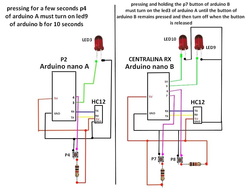
hello everyone, I have a problem that I can't figure out, I have two arduino nanos and two hc12s that I use to communicate with each other, my problem concerns the pressed button, I would like that when I hold down the button for example on the arduino A the state of the button pressed on arduino B is transmitted and consequently a led lights up on arduino B for the time that the arduino A button remains pressed while arduino B should have a button that makes me turn on the arduino A led for 10 seconds and then switch off, this via the hc12 modules

can anyone help me figure out how to do it? I enclose code that I had prepared both part A and part B, but it doesn't work well because the button can't always be intercepted in the loop.

#include <SoftwareSerial.h>
int stato = LOW;
const int ledPin9 = 9;
const int ledPin10 = 10;
const int buttonPin7 = 7;
const int buttonPin8 = 8;
int buttonState7 = 0; 
int buttonState8 = 0; 
void setup() {
    Serial.begin(9600);


     pinMode(LED_BUILTIN, OUTPUT);
   pinMode(buttonPin7, INPUT_PULLUP);
    pinMode(buttonPin8, INPUT_PULLUP);
    pinMode(ledPin9, OUTPUT);
    pinMode(ledPin10, OUTPUT);
}

void loop() {

  buttonState7 = digitalRead(buttonPin7);//accende a stato 2/3
 buttonState8 = digitalRead(buttonPin8);//accende a stato 4/5
 if (buttonState7 == LOW) 
           {          
          Serial.print("P2SON"); 
          delay(1500);           
              }
          if (buttonState7 == HIGH) 
        {
              Serial.print("P2SOFF"); 
          delay(1500); 
                   
         }
                    
          if (buttonState8 == LOW) 
           {
          Serial.print("P4SON");
          delay(1500); 
           }
          if (buttonState8 == HIGH) 
        {
              Serial.print("P4SOFF"); 
          delay(1500); 
          
         }

   if(Serial.available() > 0)    
    {
        String input = Serial.readString();
        if(input == "P1")
        {
          digitalWrite(ledPin9, HIGH);  // Turn the LED on (Note that LOW is the voltage level
          delay(10000);                      // Wait for a second
          digitalWrite(ledPin9, LOW);  // Turn the LED off by making the voltage HIGH
          //delay(500);         
            }
            if(input == "P2")
        {
          digitalWrite(ledPin9, HIGH);  // Turn the LED on (Note that LOW is the voltage level
          delay(10000);                      // Wait for a second
          digitalWrite(ledPin9, LOW);  // Turn the LED off by making the voltage HIGH
         // delay(500);         
            }
             if(input == "P3")
        {
          digitalWrite(ledPin9, HIGH);  // Turn the LED on (Note that LOW is the voltage level
          delay(10000);                      // Wait for a second
          digitalWrite(ledPin9, LOW);  // Turn the LED off by making the voltage HIGH
          //delay(500);         
            }
             if(input == "P4")
        {
          digitalWrite(ledPin10, HIGH);  // Turn the LED on (Note that LOW is the voltage level
          delay(10000);                      // Wait for a second
          digitalWrite(ledPin10, LOW);  // Turn the LED off by making the voltage HIGH
         // delay(500);         
            }
             if(input == "P5")
        {
          digitalWrite(ledPin10, HIGH);  // Turn the LED on (Note that LOW is the voltage level
          delay(10000);                      // Wait for a second
          digitalWrite(ledPin10, LOW);  // Turn the LED off by making the voltage HIGH
         // delay(500);         
            }
             if(input == "P6")
        {
          digitalWrite(ledPin10, HIGH);  // Turn the LED on (Note that LOW is the voltage level
          delay(10000);                      // Wait for a second
          digitalWrite(ledPin10
          , LOW);  // Turn the LED off by making the voltage HIGH
         // delay(500);         
            }
        }


    }

#include <SoftwareSerial.h>

const int buttonPin = 4;
int buttonState = 0; 
int dalia = 0;
const int ledPin3 = 3;
void setup() {
    Serial.begin(9600);
   
      pinMode(ledPin3, OUTPUT);
      pinMode(buttonPin, INPUT);
}

void loop() {

  buttonState = digitalRead(buttonPin);
   if (buttonState == LOW) {
    // turn LED on:
    Serial.print("P2");
     delay(1500);
  } 

    if(Serial.available() > 0)
    {
        String input = Serial.readString();
        if(input == "P2SON")
        {
          digitalWrite(ledPin3, HIGH);
          delay(100);
           }
           if(input == "P2SOFF")
            {
              digitalWrite(ledPin3, LOW);
          delay(100);
           }

                      
         //if (dalia == 0) {
              
           // Serial.println("P2S ACCESO A STATO");
             //digitalWrite(ledPin3, HIGH);
              //dalia=1;
         //}else{
         //Serial.println("P2S SPENTO A STATO");
            // digitalWrite(ledPin3, LOW);
              //dalia=0;

        
          }               
        
       }
void off(){
  
}

Hello

The radio modules aren´t connected logical to the sketch.

Post a schematic to see how we can help.

Firstly, test your NANO-NANO SUART-based setup without HC12 Modules and then place the HC12 Modules.

1. Build the following setup of Fig-1. The LED0 of NANO will remain ON as long as the Button0 of UNO is kept closed/pressed.
uartUnoNano
Figure-1:

2. Upload the following sketches.
UNO Sketch:

#include<SoftwareSerial.h>
SoftwareSerial SUART(10, 11); //SRX = 10, STX = 11

void setup()
{
  Serial.begin(9600);
  SUART.begin(9600);
  pinMode(2, INPUT_PULLUP);

}

void loop()
{
  if (digitalRead(2) == LOW)
  {
    SUART.print('1');
  }
  else
  {
    SUART.print('0');
  }
  delay(1000);
}

NANO Sketch:

#include<SoftwareSerial.h>
SoftwareSerial SUART(10, 11);

void setup()
{
  Serial.begin(9600);
  SUART.begin(9600);
  pinMode(2, OUTPUT);
}

void loop()
{
  byte n = SUART.available();
  Serial.println(n);
  if (n != 0)
  {
    char y = SUART.read();
    if (y == '1')
    {
      digitalWrite(2, HIGH);
    }
    else
    {
      digitalWrite(2, LOW);
    }
  }
}

3. Press and hold Button0 of UNO. Check that LED0 of ANNO remains ON. Release Button0 and check that LED0 has gone to OFF state.

4. Connect HC12 Modules with UNO and NANO.
5. Repeat Step-3.

your code is ok but i need installa two button in arduino B, when insert code for the button i have a problem for then pressed and light on led in arduino A, i have this code for Arduino B

type or paste code here

#include<SoftwareSerial.h>
SoftwareSerial SUART(10, 11); //SRX = 10, STX = 11

void setup()
{
Serial.begin(9600);
SUART.begin(9600);
pinMode(2, INPUT_PULLUP);
pinMode(3, INPUT_PULLUP);
pinMode(4, OUTPUT);
pinMode(5, OUTPUT);
}

void loop()
{
if (digitalRead(2) == LOW)
{
SUART.print('1');
}
else
{
SUART.print('0');
}
if (digitalRead(3) == LOW)
{
SUART.print('2');
}
else
{
SUART.print('0');
}

delay(100);

byte n = SUART.available();
Serial.println(n);
if (n != 0)
{
char y = SUART.read();
if (y == '4')
{
digitalWrite(4, HIGH);
delay(10000);
digitalWrite(4, LOW);
}
if (y == '5')
{
digitalWrite(5, HIGH);
delay(10000);
digitalWrite(5, LOW);
}
}
}

@fifiddu
Referring to diagram of post #4 (re-drwan below in Fig-1) --


Figure-1:

1. You mean -- if Button-P4 of NANO-A remains closed for 5-sec (as you have said few seconds), LED9 of NANO-B will remain ON for 10 secs.

2. You mean -- if Button-P7 of NANO-B remains closed, only then LED3 of NANO-A will turn ON and remains ON until utton-P7 is released.

3. What are the purposes of Button-P8 and LED10 of NANO-B?

4. Please, use code tags (</>) when posting codes.

5. Example-1 (Create sketch to check Button-P4 remains closed for at least 5-sec and then turn ON LED3.)

unsigned long prMillis = 0;

void setup()
{
  pinMode(4, INPUT_PULLUP);
  pinMode(3, OUTPUT);

  while (1) //keep executing following codes until condition is true and then break loop
  {
    if (digitalRead(4) == LOW)
    {
      if (millis() - prMillis >= 5000)
      {
        digitalWrite(3, HIGH);
        break;
      }
    }
  }
}

void loop() {}
1 Like

In the meantime, thank you for answering me, the arduino nano B led 10 will turn on via a third arduino nano equal to nano A but called arduino C but it will have to turn on with a different value to avoid turning on both led9 and led10 together, while the button P8 will have to turn on a led in the same way as button P7 but on another arduino called C and that does not turn on arduino A at the same time I hope I was clear.

1 Like

hello, thanks for your advice, in the end I solved the problem by changing some parameters, all good

Cross-Posting HERE ... thread closed.

Guglielmo