Hello all,
Been a while since I've been here. Having lots of family issues. But anyhoo, not going to bore you with details. I'm working on several projects (garage door opener, GPS Tracker, Laser Tripwire) which are all working flawlessly thanks to your previous guidance, but I've ran into a problem. On all of these projects I added a 3.7 volt li-ion battery so I can move the unit from one place to another without losing power. The battery isn't meant to last a long time, just long enough to unplug it and move it to another location.
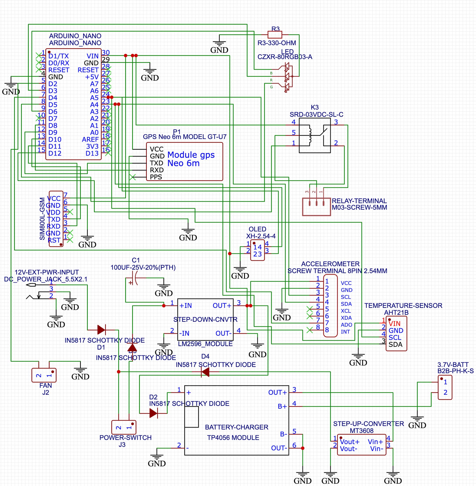
I'm using a TP4056 charging module to charge the battery, which as far as I know IS charging, but when I unplug the unit the power is lost. I've added a photo from the website EasyEDA of my schematic. Please forgive me for my lack of knowledge in the schematic design. I wanted to make a PCB, and it works great except for the design lol.
I've also included my code, which is really inconsequential I think, but I figured that someone may ask for it. Thank you sincerely for any direction you all can give me.

#include <TinyGPS++.h>
#include <SoftwareSerial.h>
SoftwareSerial GSM(10, 11);
SoftwareSerial neo(8, 9);
String textMessage;
String lampState;
String weekday = "";

double lati = 0;
double longi = 0;
double speed = 0;
uint32_t direction = 0;
uint32_t num_sat = 0;
double elevation = 0;

#define redLed    3
#define greenLed  5
#define blueLed   6
const int relay = 12;
TinyGPSPlus gps;
const int timezone_hours = -4;
const int timezone_minutes = 0;
int utcsecond = 0;
int utcminute = 0;
int utchour = 0;
int utcday = 1;
int utcmonth = 1;
int utcyear = 2021;
int localminute = 0;
int localhour = 0;
int localday = 1;
int localmonth = 1;
int localyear = 2021;

uint32_t daycount = 0;

void setup() {

  pinMode(redLed, OUTPUT);
  pinMode(greenLed, OUTPUT);
  pinMode(blueLed, OUTPUT);
  pinMode(relay, OUTPUT);
  digitalWrite(redLed, HIGH);
  delay(500);
  digitalWrite(redLed, LOW);
  digitalWrite(greenLed, HIGH);
  delay(500);
  digitalWrite(greenLed, LOW);
  digitalWrite(blueLed, HIGH);
  delay(500);
  digitalWrite(blueLed, LOW);
  digitalWrite(relay, HIGH);
  Serial.begin(115200);
  GSM.begin(9600);
  neo.begin(9600);
  GSM.listen();
  delay(5000);
  digitalWrite(greenLed, HIGH);
  Serial.print("GSM ready...\r\n");
  GSM.print("AT+CMGF=1\r\n");
  delay(1000);
  GSM.print("AT+CNMI=2,2,0,0,0\r\n");
  delay(1000);
  digitalWrite(greenLed, LOW);

}


void loop() {
  GSM.listen();
  delay(2);
  while (GSM.available() > 0) {
    digitalWrite(blueLed, HIGH);
    textMessage = GSM.readString();
    Serial.print(textMessage);
    delay(10);
    digitalWrite(blueLed, LOW);
  }
  neo.listen();
  if (textMessage.indexOf("ON") >= 0) {
    String array_string[20];
    string_splitting(textMessage,array_string,'\"');
    String NUMBER = array_string[1];
    digitalWrite(relay, LOW);
    lampState = "ON";
    Serial.println("Vehicle set to ON\r\n");
    textMessage = "";
    GSM.println("AT+CMGS=\"" + NUMBER + "\"\r");
    delay(500);
    GSM.print("Vehicle set to ON\r");
    GSM.write(0x1a);
    delay(1000);
    GSM.println("AT+CMGD=1,4");
    digitalWrite(redLed, LOW);
    digitalWrite(greenLed, HIGH);
    delay(5000);
    digitalWrite(greenLed, LOW);

  }
  if (textMessage.indexOf("OFF") >= 0) {
    String array_string[20];
    string_splitting(textMessage,array_string,'\"');
    String NUMBER = array_string[1];
    digitalWrite(relay, HIGH);
    lampState = "OFF";
    Serial.println("Vehicle set to OFF\r\n");
    textMessage = "";
    GSM.println("AT+CMGS=\"" + NUMBER + "\"\r");
    delay(500);
    GSM.print("Vehicle set to OFF\r");
    GSM.write(0x1a);
    delay(1000);
    GSM.println("AT+CMGD=1,4");
    digitalWrite(greenLed, LOW);
    digitalWrite(redLed, HIGH);
    delay(5000);
    digitalWrite(redLed, LOW);
  }

  if (textMessage.indexOf("GETLOC") >= 0) {
    Serial.println("_____________________________________");
    smartDelay(1000);
    String array_string[20];
    string_splitting(textMessage,array_string,'\"'); //
    String NUMBER = array_string[1];
    Serial.println("GPS data Recived\r\n");
    textMessage = "";

    // get some data and store it to variables
    speed = gps.speed.mph();
    direction = gps.course.value();
    num_sat = gps.satellites.value();
    elevation = gps.altitude.feet();

    Serial.print("Speed: ");
    Serial.print(speed);
    Serial.println(" Miles Per Hour");
    Serial.print("Number of Satellites: ");
    Serial.println(num_sat);
    Serial.print("Raw course in 1/100 degrees = ");
    Serial.println(direction);
    Serial.print("Elevation: ");
    Serial.print(elevation);
    if (elevation > 0) Serial.println(" ASL");
    if (elevation < 0) Serial.println(" BSL");
    Serial.println("_____________________________________");
    GSM.println("AT+CMGS=\"" + NUMBER + "\"\r");
    delay(500);
    String pesan = "https://maps.google.com/?q=" + String(lati, 8) + "," + String(longi, 6);

    if (gps.time.isValid()) {
      // OK, so here we grab the UTC date and time
      utcyear = gps.date.year();
      utcmonth = gps.date.month();
      utcday = gps.date.day();
      utchour = gps.time.hour();
      utcminute = gps.time.minute();
      utcsecond = gps.time.second();

      Serial.println("UTC =  "+String(utchour)+":"+String(utcminute)+":"+String(utcsecond));

      localyear = utcyear;
      localmonth = utcmonth;
      localday = utcday;
      localhour = utchour + timezone_hours;
      localminute = utcminute + timezone_minutes;
      doLocalTimeCarries();
    }

    GSM.print("Date: ");
    daycount =  (localyear - 1601) * ((uint32_t)365);
    daycount += (localyear - 1601) / 4;
    daycount -= (localyear - 1601) / 100;
    daycount += (localyear - 1601) / 400;
    for (int i = 1; i < localmonth; i++) {
      daycount += days_in_month(localyear, i);
    }
     daycount += localday;
    switch (daycount % 7) {
      case 0:
        GSM.print("Sun  ");
        break;
      case 1:
        GSM.print("Mon   ");
        break;
      case 2:
        GSM.print("Tue   ");
        break;
      case 3:
        GSM.print("Wed   ");
        break;
      case 4:
        GSM.print("Thu   ");
        break;
      case 5:
        GSM.print("Fri   ");
        break;
      case 6:
        GSM.print("Sat   ");
        break;
      default:
        GSM.print("Bad   ");
        break;
    }
    GSM.print(localmonth);
    GSM.print("/");
    GSM.print(localday);
    GSM.print("/");
    GSM.println(localyear);
    GSM.print("Time: ");
    if (localhour < 10) GSM.print("0");
    GSM.print(localhour);
    GSM.print(":");
    if (localminute < 10) GSM.print("0");
    GSM.print(localminute);
    GSM.print(":");
    if (utcsecond < 10) GSM.print("0");
    GSM.println(utcsecond);
    GSM.print("Speed: ");
    GSM.print(speed);
    GSM.println(" MPH");
    GSM.print("Direction: ");
    // GSM.println(direction / 100.0);
    if  (direction < 1125) GSM.println("North");
else if (direction < 3375) GSM.println("NNE");
else if (direction < 5625) GSM.println("NE");
else if (direction < 7875) GSM.println("ENE");
else if (direction < 10125) GSM.println("East");
else if (direction < 12375) GSM.println("ESE");
else if (direction < 14625) GSM.println("SE");
else if (direction < 16875) GSM.println("SSE");
else if (direction < 19125) GSM.println("South");
else if (direction < 21375) GSM.println("SSW");
else if (direction < 23625) GSM.println("SW");
else if (direction < 25875) GSM.println("WSW");
else if (direction < 28125) GSM.println("West");
else if (direction < 30375) GSM.println("WNW");
else if (direction < 32625) GSM.println("NW");
else if (direction < 34875) GSM.println("NNW");
else GSM.println("North");
    GSM.print("Number of Satellites: ");
    GSM.println(num_sat);
    GSM.print("Elevation: ");
    if (elevation >= 0) {
      GSM.print(elevation);
      GSM.println(" Feet ASL");
    }
    else {
      // negative elevation
      GSM.print(-elevation);
      GSM.println(" Feet BSL");
    }
    // GSM.print(" Feet");
    // if (elevation > 0) GSM.println(" ASL");
    // if (elevation < 0) GSM.println(" BSL");
    GSM.print(pesan);
    GSM.write(0x1a);
    delay(1000);
    GSM.println("AT+CMGD=1,4");
  }
}


static void smartDelay(unsigned long ms) {
  unsigned long start = millis();
  do {
    neo.listen();
    delay(2);
    while (neo.available())
      gps.encode(neo.read());
  } while (millis() - start < ms);
  lati = gps.location.lat();
  longi = gps.location.lng();
  Serial.println(lati, 8);
  Serial.println(longi, 6);
}

void string_splitting(String splitMsg, String bb[], char delimiter) {
  int counter = 0 ;
  for ( int i = 0 ; i < splitMsg.length() ; i ++ ) {
    if ( splitMsg.charAt(i) == delimiter ) {
      counter++;
    }
    else {
      bb[counter] +=  splitMsg.charAt(i) ;
    }
  }
}


void doLocalTimeCarries() {
  // This function does the carries for the local time:
  // it exchanges 60 minutes for 1 hour,
  // 24 hours for 1 day, and so forth.
  if (localminute < 0) {
    // not enough minutes, so move back to previous hour
    localminute += 60;
    localhour--;
  }
  else if (localminute >= 60) {
    // too many minutes, so move forward to next hour
    localminute -= 60;
    localhour++;
  }
  if (localhour < 0) {
    // not enough hours, so move back to previous day
    localhour += 24;
    localday--;
  }
  else if (localhour >= 24) {
    // too many hours, so move forward to next day
    localhour -= 24;
    localday++;
  }
  if (localday < 1) {
    // not enough days, so move back to previous month
    localmonth--;
    if (localmonth < 1) {
      // not enough months, so move to previous year
      localmonth += 12;
      localyear--;
    }
    localday += days_in_month(localyear, localmonth);
  }
  else if (localday > days_in_month(localyear, localmonth)) {
    // too many days, so move forward to next month
    localday -= days_in_month(localyear, localmonth);
    localmonth++;
    if (localmonth > 12) {
      // too many months, so move to next year
      localmonth -= 12;
      localyear++;
    }
  }
}

int days_in_month (int y, int m) {
  // Essential helper function for advancing time:
  // it gives the number of days in month m of year y.
  // Fourth, eleventh, ninth, and sixth,
  // thirty days to each we fix.
  if ((m==4)||(m==11)||(m==9)||(m==6)) return 30;
  // Every other, thirty-one,
  // except the second month alone,
  if (m!=2) return 31;
  // which hath twenty-eight, in fine,
  // till leap-year give it twenty-nine.
  if ((y%400)==0) return 29; // leap year
  if ((y%100)==0) return 28; // not a leap year
  if ((y%4)==0)   return 29; // leap year
  return 28; // not a leap year
}