A couple more (this is hard work on an iPad!)...
Heh, HAM still use RTTY these days?
Radio Amateurs do, but no idea what pieces of meat do. ![]()
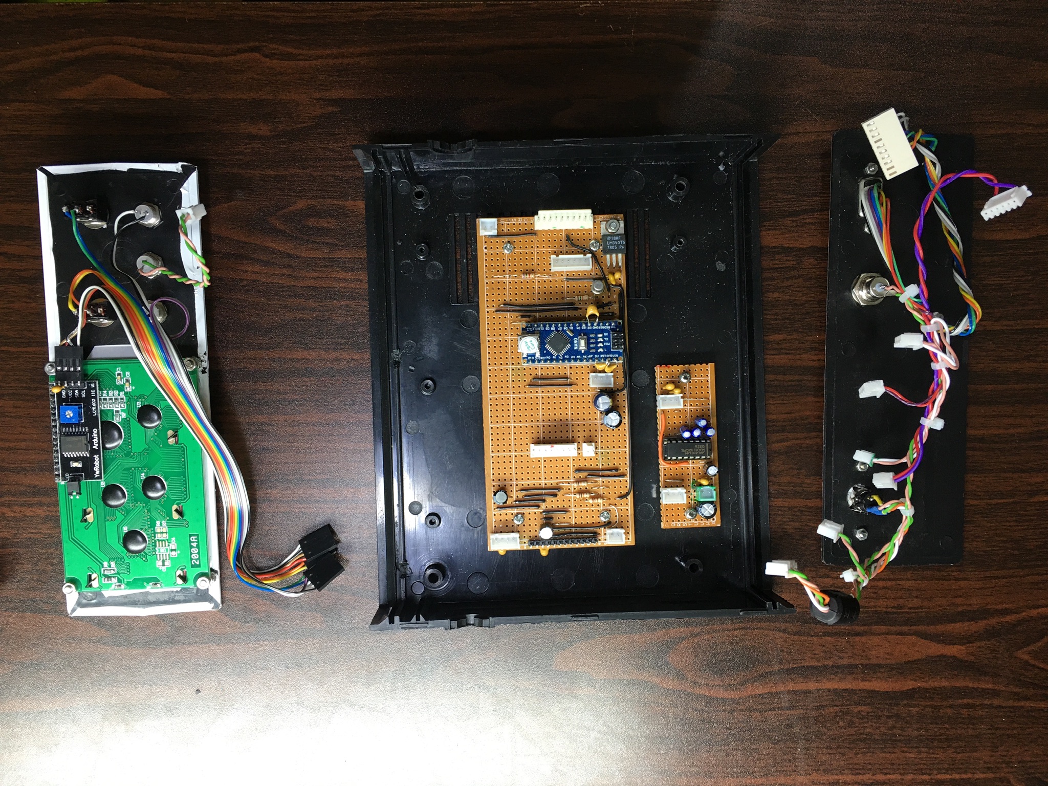
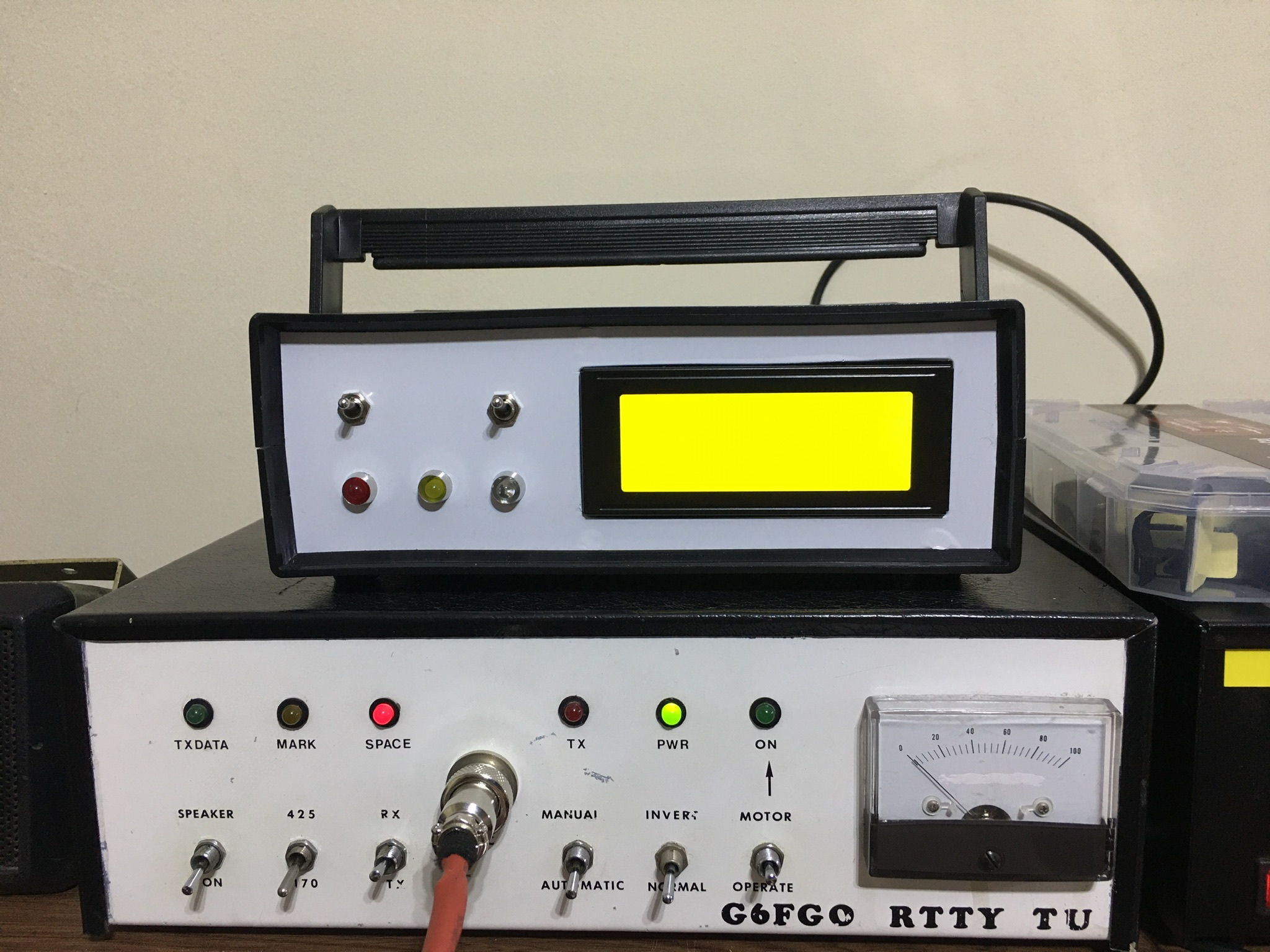
That is what the unit is for until I can find another teleprinter. This is an electronic version of one. It accepts a PS/2 keyboard for transmit. Still lots of mods to do to, it is quite basic currently although useable.
AJLElectronics:
A couple more (this is hard work on an iPad!)...
Nice work.
Have you worked with #30 AWG solid wire wrap wire on your proto typing boards?
You may like this topic post #692 and on:
https://forum.arduino.cc/index.php?topic=445951.690#bot
See also post #47:
https://forum.arduino.cc/index.php?topic=445951.msg3093342#msg3093342
"Very nice!"
Just a quick lash up really.
"For connections to the Nano do you have wires running as vias on the other side of the perf board?"
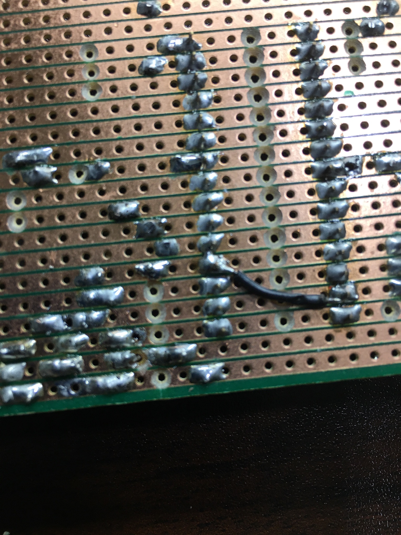
Have you not come across stripboard before? The photo shows some after being badly soldered. In fact it is the reverse of the main board in the terminal unit I have just shown you. If you look carefully you might be able to see why it didn't work first time!
"What are some good sources for ribbon cable like that? (I'm in US)"
It must be simple to find, just do a search for ribbon cable.
"Do you crimp your own connectors onto the ribbon cable?"
Yes, you should maybe look for a kit. I have bought a Preciva crimp tool and assorted connectors. Try a search for that. It also comes with some pretty ribbon!


Thanks for all the tips. This is great.
Hint. Don't take a working project apart. Duplicate it in place in your final product. Mistakes will happen and will be difficult to find if you don't have a reference.
Just a quick note on my project... the inclusion of the breadboard is a little misleading. It's only serving up 5V and Ground for the components, and seats the IR receiver module. Everything else is connecting directly into the Nano. (I actually tore down and migrated the entire project from a Mega to the Nano last night in about 15 minutes).
HOWEVER... I do have other projects (actually still sitting on the bench!) which DO have a lot happening on the breadboard, so this advice makes a lot of sense. I've been hesitant to break them down out of this very same concern.
Hello Steve.
I've been developing a GPS speedometer and have had the same challenges of moving from prototype to a stable portable and compact device. It works well as a clock.
My setup would be interesting to you but just an hour ago I desoldered it all in readiness of reassembling it with a new base board.
I really dislike the breadboard and jumpers setup. Next time I would go straight to a perf board for the prototype stage. Soldered connections eliminate a heap of problems (as long as the soldering is good). I found jumpers introduce a voltage drop that ruins the GPs performance.
I would use a perf board setup for the prototyping and testing and program development. I would develop in parallel the final product.
I'm using a 3D printed base board designed to fit a shop bought box. I'm embedding headers in the board and connecting display and GPS and Bluetooth to the headers with ribbon cable. It works. I'm now fine tuning it. The greatest time waster come from flaky connections. Solder wherever you can and have deep connections with headers. Strengthen connectors with hot melt glue.
It is time consuming to fit the design into a small case. I think I would rather go for a larger than necessary case and enjoy the excess space.
I found phone chargers are not clean enuf for the GPS. I'm using a power bank or a PC/car UBS port.
John.
Here's a pic of my project. Far fewer components than the ones above.

The 3D printed board is an advance on a breadboard, but not as polished as a custom PCB. Connections under the board are by hookup wire. The board (yellow) fits just right into the grey box. It took much effort to squeeze it all into th ebox, but the end result will be good.
I swear bad connections are the greatest time wasters. I'm still an amateur at this.
John.
John, thanks for your insights.
I found jumpers introduce a voltage drop that ruins the GPs performance.
That's really odd. I haven't had any of these problems. I have 5.08V on the + side of the Apple USB charger, and it only drops to 5.06V on the VCC pin on my GPS module. (I'm powering directly and not via the nano.) I've found the genuine OEM Apple USB charging brick is rock solid.
I'm embedding headers in the board and connecting display and GPS and Bluetooth to the headers with ribbon cable.
How are you connecting the ribbon cable to your headers? Are you doing your own connectors with a crimp tool or some other approach?
Steve,
It's good that your are monitoring the volts at the GPS module. I found 4.8V is the level at which the module under performs. If you've got 5V then that shud be ok. If the GPs output is steady then it's ok.
I found the 5V pin on the Nano (non genuine) is more like 4.8V, so I power the GPS directly from a power bank.
I solder the ribbon cable wires to header pins. The header then connects with a complimentary header embedded in the board. I strengthen the ribbon cable with glue. I still get flaky connections.
Earlier you mentioned desoldering the headers on a Nano. I destroyed one in attempting that. It doesn't take much effort with soldering iron, solder sucker and solder wick to remove the tiny metal pad at the pin holes.
How do you think you will proceed?
John.
I agree with you on the desoldering... I would definitely buy new Nanos without the headers attached before I attempt to desolder 30 pins! They are so cheap anyway!
One of the first things I’ve done just last night after thinking about this is mapping out my pin usage on the Nano to minimize crossovers.
I discovered, for example, that I was using pin D5 to sense the SQW output of the RTC module. But the RTC connects to the I2C pins on A5 and A4 on the other side of the board! So I’ll reconfig my sketch and rewire to use A3(D17) for sensing which is right next to the other 2 pins.
Similarly I originally had my GPS PPS output connected to D4 on the Nano. I’m going to move that over to D2 to get it close to the TX and RX pins, and shift my IR receiver interrupt from D2 over to D3.
Inspired by some of the posts above, I’m also likely to solder the Nano into a PCB that has + and - rails already connected and then solder wires from the various modules onto the board. (I ordered these boards https://www.amazon.com/gp/aw/d/B07ZV8FWM4). I think this will help a lot.
I also ordered some 24awg solid core hookup wire to help with connections.
I’m going to hold off on buying crimpers and connectors for this project as after I looked at the number and placement of my connections I’m not sure I’d gain a lot — but I am researching what items to get for future projects where I might want to make my own connectors. Mounting the Nano on a PCB should go a long way for this project.
On one project (semi - permanent) I had:
5 Breakout boards all with pins soldered in:
- Arduino M0
- SD Card
- RTC module
- MAX31855 T/C module
- OLED display
I cut and assembled duPont jumpers with multiple connectors as needed. For instance the SPI connectors had three female ends so I could just plug them into the associated boards.
I also purchased a box of dupont connectors on ebay. I took the above jumpers and where needed, removed the single (usually female) housing and plugged the wires into a 4, 5 way or 6 way dupont connector.
I then used double sided foam tape to hold them to a plastic box.
If it were permanent I would likely design a custom PCB (I use Kicad) and plug all the boards into it.
John
The way to desolder headers etc is to destroy the plastic links first. Then you can heat and remove each pin one at a time. When clear, use desolder wick to clean the holes out.
AJLElectronics:
The way to desolder headers etc is to destroy the plastic links first. Then you can heat and remove each pin one at a time. When clear, use desolder wick to clean the holes out.
De-soldering needles work too if there is room around the header pin in the hole they are soldered.
Before I would de-solder a row of pins, I would just solder a wire to the ones I needed and leave the header intact.
Not that is cannot be done but it entails some risk and a frustration factor with IMHO little gained.
I also purchased a box of dupont connectors on ebay. I took the above jumpers and where needed, removed the single (usually female) housing and plugged the wires into a 4, 5 way or 6 way dupont connector.
John - thanks for tip. I just watched a video on YouTube yesterday that described this exact approach. I bought the empty connector housings yesterday so I can do it.
I also decided I’m going to solder 2 rows of female headers to the PCB so I can just plug the Nano in. Will allow me to swap out the Nano very easily in the future should the need ever arise.
I don't think you need to solder the entire row of pins to the board (they look good). Just the ones that are to be connected to other components.
John.
HillmanImp:
I don't think you need to solder the entire row of pins to the board (they look good). Just the ones that are to be connected to other components.John.
Great tip, thanks!
I think you could use the practice.