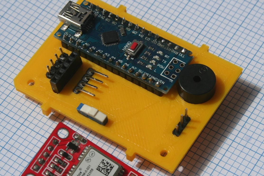
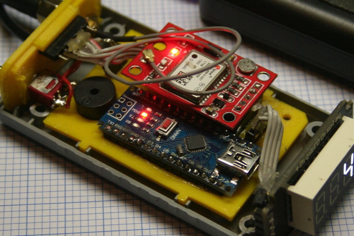
I've made a new 3D printed board. This started off experimentally to just see what could be achieved. I've come to think it provides a practical means of assembling a collection of components. There's only three components to be inserted into this board -- Nano, GPS and buzzer. The short rectangular slots are for header blocks. The outline is designed to fit into a shop-bought enclosure.
Will post more pix as I build it.
Has anyone else tried anything similar with 3D printing?
John.
What's the benefit ? You can mount any boards
on stand-offs. You can mount panel mount switches and buttons by drilling holes. What is it you are
avoiding or eliminating with a 3D board (which is not a circiut board.
The lighting controller shown in Reply #3 had
about 15 pots, 30 pushbuttons and 25 toggle switches. Deburring the holes took much more time than drilling the holes.
Yes, it's not a circuit board. I'll call it a baseboard.
I don't know if there's a worthwhile benefit. It's a different approach that I want to explore. When the device is complete we can review it.
John.
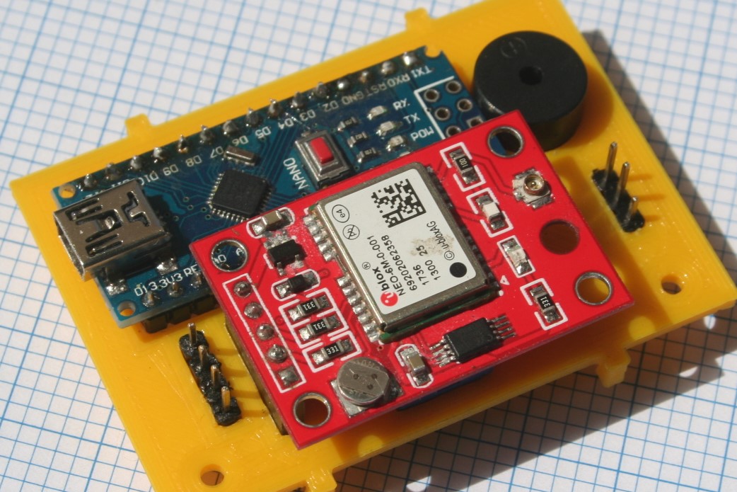
Some pix as I assembled the parts into the baseboard:
That looks useful.
Of course the same thing could be accomplished by using standoffs and a perfboard
if you don't have a 3D printer. The male headers can be mounted on it. the standoffs only require
drilling holes. It wouldn't look as nice as the 3D printed board but most people don't have 3D printers.
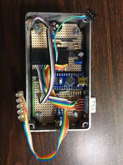
The underside after installing hookup wires. My soldering isn't pretty.
Here is one of mine that is under construction...
I'm late to the party so maybe this was suggested earlier, but what about using $5 PCBs from someplace like jlcpcb or seeedstudio? Eagle is super easy to use and PCBs clean up messy installs.
Nice !
You're a pro now !
Robert
Power_Broker:
I'm late to the party so maybe this was suggested earlier, but what about using $5 PCBs from someplace like jlcpcb or seeedstudio? Eagle is super easy to use and PCBs clean up messy installs.
OP here.
This is a great idea, and some folks did allude to it earlier. I've decided for this current application I'm working on, I will probably do best with making some dupont wire plugs using housings and putting this on a protoboard.
However, this thread did inspire me to start a new project to learn how to make my own PCB. I'm working on a programmer project now using EasyEDA which I will produce at JLCPCB. I've had a lot of fun and learned a lot digging into this side of the hobby.
Having done it a bit of it, I can definitely say it's a no-brainer in terms of making life easy. I thought it would be a lot harder to do, but was very pleased to see how relatively easy it is.
HillmanImp:
The underside after installing hookup wires. My soldering isn't pretty.
Most of the difficulty in making things neat is your poor choice in hookup wire. That looks like perhaps 20 gauge thermostat wire, far bigger than it needs to be, that stuff is miserable to work with on a good day. Proper tinned 26,28 and even 30 gauge solid hookup wire is more appropriate for point to point wiring such as you’re doing.
30 gauge “wire wrap” wire is available for cheap on eBay, 1000 foot spools for less than $10. It’s not proper wire for real wire wrapping as it has pvc insulation but it’s perfect as logic hookup wire, besides, no one really does true wire wrapping these days. Well, almost no one.
Thanks WhatsThat.
I'll go searching for alternative wire. I don't think I need a 1000 ft roll. :o
John.
You can get spools of 8 colors, 125 feet of each color. It’s kind of a pain the way they package it but for less than $5 shipped, the only downside is the wait time. You can get it for $8 directly from us sellers if you don’t want to wait. Search eBay for ”8 color 30AWG”.
https://www.ebay.com/itm/30AWG-0-25mm-280M-Tin-Plated-Copper-Wire-Wrapping-Insulation-Test-Cable-8-Color/193176923494
Completed board with components installed; 3D printed end plate; all fitted into shop-bought housing:
Finished gadget:
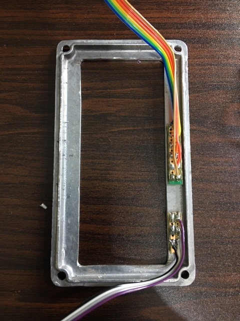
view of end plate; HC-05 Bluetooth module inserted:
device in operation; 3D printed hood to shade display:
Now that I've completed the device using a 3D printed base board, I can compare this approach to using a perf board.
First, as a 3D print enthusiast I found this a worthwhile exercise in itself, whether or not it had advantages over a perf board. It was a new challenge and the end result is now in a working device.
Perf boards are readily available -- no printing required. They have to be cut to fit the housing. They are thin and stiff making and more robust than a 3D printed board, but that isn't a big deal.
I think the soldering task is neither easier nor harder with the 3D print. For me, the end result for both is not going to be pretty until I improve my soldering. More supple wire would help as WhatsThat recommended.
It's not difficult to design the 3D print and it can be designed to perfectly fit a housing. This one took about 40 minutes to print. Easy to make another if you ruin it in the soldering.
I think a perf board as used by AJL is the superior option, but i would encourage those with access to a 3D printer to have a go and see if the method can add some real advantage. The 3D printed end plate is definitely a good thing. It was easy to make the openings to take all the connecting components. A cut and drilled stiff board would be harder to make with precision.
John.