I am new to electronics am currently trying to connect my Arduino to a PSU which converts AC from my wall to DC for the arduino. I have a DPST 4 pin switch that I want to have in between the 3 pin socket and the PSU that ways I can turn the arduino and PSU off without breaking ground connection.
My first setup I only connected the live wire to the switch while ground and neutral were wired directly to the PSU from the socket, yet this setup leaked a significant amount of voltage on the plastic parts of the switch I am supposed to touch. I am now wondering if I am supposed to connect the neutral wire to the switch too. The switch I am using is rated for up to 120volts at 16amps and my test setup was definitely not pulling the maximum power as it was powering a single LED as a test.
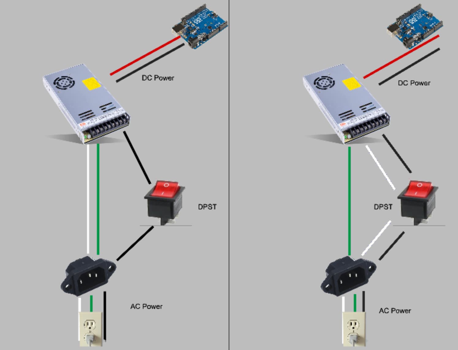
Should I try the setup as pictured on the right or should I buy a new switch?
It doesn't break ground connection as long as the Arduino is grounded to the PSU. Everything in the PSU is all grounded to its chassis anyway. There's no need for the switch at all if you are wanting to turn off the Arduino and PSU at the same time, anyway.
Why not just plug the PSU into a switched power bar? Safer than playing around with mains.
If there is a voltage potential with the power supply (using the left circuit), the AC outlet is not wiring properly.
Back in your fuse box, the GND and Neutral wires are connected to the same earth conductor, i.e. at the same potential. The electrician might have swapped the Hot and Neutral on the outlet.
How did you determine this. Your drawing is not correct. White goes to L1 or N, Black goes to L2 or line. Green goes to ground. Normally these three terminals are on the left of the PSU (Power Supply Unit) as shown in your drawing. Show the terminal strip or better yet a schematic.
Hello, this was determined using a voltage detector pen and later a multimeter set to the AC voltage measurement setting. the drawing was more of a general setup to make my description about how the switch was incorporated more clear rather then the specifics of how everything was wired, I apologize if it may have caused any confusion. The actual wires are lined up correctly into the PSU terminal (ground, neutral line on a meanwell LRS200) and the PSU itself isn't experiencing any issues, just the switch leaking voltage.
Plastic is an insulator at mains voltages. Is the plastic contaminated with something. A voltage detection will detect when there is a voltage in the area, which could be behind an insulator. Using a multimeter is the best way. Follow @jim-p suggestions.
In that case the switch is not safe for this application.
Can you show us a photo of your setup? And are you complying with the need for the whole circuit to be double insulated and /or any exposed parts grounded?
True - but that doesnt mean that they have the same potential everywhere. I once measured 70V of 13Mhz on a neutral.