Hi,
can I use the Pulse Sensor on a Arduino Leoardo without Processing?
Thank you
Hi,
can I use the Pulse Sensor on a Arduino Leoardo without Processing?
Thank you
What Pulse Sensor would that be ?
Do you have some Idea for my Problem ?
Sandmannn:
Do you have some Idea for my Problem ?
When I look at the Arduino code example for that sensor at Pulse Sensor Amped – World Famous Electronics llc. I see that the sensor is read by "analogRead()" within a timer interrupt:
ISR(TIMER2_COMPA_vect){
  Signal = analogRead(pulsePin);
Every Arduino board is able to deal with timer interrupts and the analogRead() function.
I even see that there are additional hints how the programming example needs to be changed to work with 32U4 Arduinos like the 'Leonardo' board:
The only other thing you will need is the correct ISR vector in the next step.
ATmega32u4 devices use ISR(TIMER1_COMPA_vect)
As far as I see, the open-source vizualizing tool/language 'Processing' is only needed for visualizing data on a PC.
As the example software comes with full source, you can off course change the source code, so that your results are not visualized with Processing, but perhaps only sent to the Arduino serial monitor or to a text LCD display.
Programming is up to you, I'd say, except you'd like to use the example program exactly how it is provided as an programming example.
Sorry but I'm quite a beginner,
so what i must change in der example software to see the heart rate in the serial monitor.
Thank you
Sandmannn:
so what i must change in der example software to see the heart rate in the serial monitor.
Both changes needed to make the sketch work with 32U4 controllers like the LEONARDO are clearly notified on the page I linked in my last reply.
Did you do those two changes regarding the use of a timer interrupt in the source code?
If you want no further processing of data with the "Processing" environment, just delete sending the "Signal" within the loop and just send BPM and IBI when they are detected:
Untested changes:
void loop(){
//  sendDataToProcessing('S', Signal);
  if (QS == true){
//    sendDataToProcessing('B',BPM);
//    sendDataToProcessing('Q',IBI);
    Serial.print(BPM);
    Serial.print('\t');
    Serial.println(IBI);
    fadeVal = 255;
    QS = false;
   }
   ledFadeToBeat();
   delay(20);
}
The sketch will only show data, if a pulse could be detected.
No pulse detected = No data sent
And also watch out for the baud rate set in the sketch: The baud rate in the sketch MUST match the baud rate in the serial monitor. Wrong baudrate = You see nothing.
Maximum baudrate for the serial monitor is 115200.
If you have problems with getting it all to work, just start with a simple sketch showing some raw data from the pulse sensor. Here is a test sketch showing raw data from an analogue input for 30 seconds:
#define PULSEPIN A0  // Pulse Sensor purple wire connected to analog pin A0

void setup() {
  Serial.begin(115200);
  Serial.println();
  Serial.println("Start reading data");
}

unsigned long lastADCsample;
unsigned long numSamples;
void loop()
{
  long now=micros();
  if (now> 30000000L) // 30000000L µs = 30 seconds
  { // stop program after 30 seconds
    Serial.print("Time: ");Serial.println(now/1000000.0,6);
    Serial.print("Samples: ");Serial.println(numSamples);
    Serial.println("Finished - END");
    while(1);
  }
  else if (now-lastADCsample>=1000)
  {
    lastADCsample+=1000;
    Serial.println(analogRead(PULSEPIN)>>2); // reduce ADC resolution to 8 bit
    numSamples++;
  }
}
If you still have trouble, give it a try, and post some seconds of data so that I can have a look what data you have.
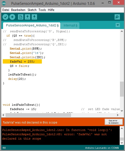
thank you for your quick response,
now i have two problems:
fadeVal = 255;
is not declared in this scope (picture in the attach)
Thank you
Sandmannn:
thank you for your quick response,now i have two problems:
I think the number of problems you have is much higher than two.
First problem: The Arduino UNO is the board for beginner 'Newbies'. All of the example sketches are made for the UNO. You purchase a different board, the LEONARDO, and many examples are NOT made for the LEONARDO as it is a bit different. So many example codes may need changes, to be adapted to the Leonardo board. Including the example for your heartbeat sensor.
Second problem: You are unable to program the changes needed. Why that? The changes needed for the Leonardo are on the page. I sent you the link!
Third problem: You never answer any queries. In my last posting I asked:
Did you do those two changes regarding the use of a timer interrupt in the source code?
You did not answer that, but instead I read:
fadeVal = 255; is not declared in this scope
and
after i uploaded the sample sketch on the arduino, the arduino is a unknown device
How can you upload a sketch that even does NOT COMPILE?
This is NOT POSSIBLE!
You can only upload a sketch if is has been compiled free of errors.
So if 'fadeval' is not declared, you must have done something with the original code, that 'fadeval' is not declared any longer. And if you afterwards could compile the sketch, you must have done some corrections or disimprovements to the worse, that the sketch could be compiled.
Fourth problem: You are sending images of screens instead of sending error messages in full text. Do not send images of error messages, but copy the text error message into the clipboard of your PC and insert the message into your forums posting!
Fifth problem: After all your mistakes you made like "uploading wrong code to the wrong board" it looks like you have locked yourself out from the Leonardo, so that you are unable to upload any sketch to the device.
So you would have to do this to get control back over your Leonardo board:
After you have managed yourself being locked out from the Leonardo, the "auto-reset upload" will not work any longer and you need the "manual reset upload".
Do you know how to do that?
OK,
third problem: 1.I have changed the timer interrupt in the source code for the leonardo.
volatile int rate[10];                    // array to hold last ten IBI values
volatile unsigned long sampleCounter = 0;          // used to determine pulse timing
volatile unsigned long lastBeatTime = 0;           // used to find IBI
volatile int P =512;                      // used to find peak in pulse wave, seeded
volatile int T = 512;                     // used to find trough in pulse wave, seeded
volatile int thresh = 512;                // used to find instant moment of heart beat, seeded
volatile int amp = 100;                   // used to hold amplitude of pulse waveform, seeded
volatile boolean firstBeat = true;        // used to seed rate array so we startup with reasonable BPM
volatile boolean secondBeat = false;      // used to seed rate array so we startup with reasonable BPM


void interruptSetup(){
  // Initializes Timer2 to throw an interrupt every 2mS.
  TCCR0A = 0x02;     // DISABLE PWM ON DIGITAL PINS 3 AND 11, AND GO INTO CTC MODE
  TCCR0B = 0x04;     // DON'T FORCE COMPARE, 256 PRESCALER
  OCR0A = 0X7C;      // SET THE TOP OF THE COUNT TO 124 FOR 500Hz SAMPLE RATE
  TIMSK0 = 0x02;     // ENABLE INTERRUPT ON MATCH BETWEEN TIMER2 AND OCR2A
  sei();                // MAKE SURE GLOBAL INTERRUPTS ARE ENABLED
}


// THIS IS THE TIMER 2 INTERRUPT SERVICE ROUTINE.
// Timer 2 makes sure that we take a reading every 2 miliseconds
ISR(TIMER1_COMPA_vect){                         // triggered when Timer2 counts to 124
  cli();                                      // disable interrupts while we do this
  Signal = analogRead(pulsePin);              // read the Pulse Sensor
  sampleCounter += 2;                         // keep track of the time in mS with this variable
  int N = sampleCounter - lastBeatTime;       // monitor the time since the last beat to avoid noise

    //  find the peak and trough of the pulse wave
  if(Signal < thresh && N > (IBI/5)*3){       // avoid dichrotic noise by waiting 3/5 of last IBI
    if (Signal < T){                        // T is the trough
      T = Signal;                         // keep track of lowest point in pulse wave
    }
  }

  if(Signal > thresh && Signal > P){          // thresh condition helps avoid noise
    P = Signal;                             // P is the peak
  }                                        // keep track of highest point in pulse wave

  //  NOW IT'S TIME TO LOOK FOR THE HEART BEAT
  // signal surges up in value every time there is a pulse
  if (N > 250){                                   // avoid high frequency noise
    if ( (Signal > thresh) && (Pulse == false) && (N > (IBI/5)*3) ){
      Pulse = true;                               // set the Pulse flag when we think there is a pulse
      digitalWrite(blinkPin,HIGH);                // turn on pin 13 LED
      IBI = sampleCounter - lastBeatTime;         // measure time between beats in mS
      lastBeatTime = sampleCounter;               // keep track of time for next pulse

      if(secondBeat){                        // if this is the second beat, if secondBeat == TRUE
        secondBeat = false;                  // clear secondBeat flag
        for(int i=0; i<=9; i++){             // seed the running total to get a realisitic BPM at startup
          rate[i] = IBI;
        }
      }

      if(firstBeat){                         // if it's the first time we found a beat, if firstBeat == TRUE
        firstBeat = false;                   // clear firstBeat flag
        secondBeat = true;                   // set the second beat flag
        sei();                               // enable interrupts again
        return;                              // IBI value is unreliable so discard it
      }


      // keep a running total of the last 10 IBI values
      word runningTotal = 0;                  // clear the runningTotal variable

      for(int i=0; i<=8; i++){                // shift data in the rate array
        rate[i] = rate[i+1];                  // and drop the oldest IBI value
        runningTotal += rate[i];              // add up the 9 oldest IBI values
      }

      rate[9] = IBI;                          // add the latest IBI to the rate array
      runningTotal += rate[9];                // add the latest IBI to runningTotal
      runningTotal /= 10;                     // average the last 10 IBI values
      BPM = 60000/runningTotal;               // how many beats can fit into a minute? that's BPM!
      QS = true;                              // set Quantified Self flag
      // QS FLAG IS NOT CLEARED INSIDE THIS ISR
    }
  }

  if (Signal < thresh && Pulse == true){   // when the values are going down, the beat is over
    digitalWrite(blinkPin,LOW);            // turn off pin 13 LED
    Pulse = false;                         // reset the Pulse flag so we can do it again
    amp = P - T;                           // get amplitude of the pulse wave
    thresh = amp/2 + T;                    // set thresh at 50% of the amplitude
    P = thresh;                            // reset these for next time
    T = thresh;
  }

  if (N > 2500){                           // if 2.5 seconds go by without a beat
    thresh = 512;                          // set thresh default
    P = 512;                               // set P default
    T = 512;                               // set T default
    lastBeatTime = sampleCounter;          // bring the lastBeatTime up to date
    firstBeat = true;                      // set these to avoid noise
    secondBeat = false;                    // when we get the heartbeat back
  }

  sei();                                   // enable interrupts when youre done!
}// end isr
void loop(){
//  sendDataToProcessing('S', Signal);
  if (QS == true){
//    sendDataToProcessing('B',BPM);
//    sendDataToProcessing('Q',IBI);
    Serial.print(BPM);
    Serial.print('\t');
    Serial.println(IBI);
    fadeVal = 255;
    QS = false;
   }
   ledFadeToBeat();
   delay(20);
}
that change, so the sketch can compile.
fourth problem:
This report would have more information with
"Show verbose output during compilation"
enabled in File > Preferences.
Arduino: 1.0.6 (Windows NT (unknown)), Board: "Arduino Leonardo"
PulseSensorAmped_Arduino_1dot2.ino: In function 'void loop()':
PulseSensorAmped_Arduino_1dot2:67: error: 'fadeVal' was not declared in this scope
fitht problem: now my arduino leonardo works again.
Sandmannn:
PulseSensorAmped_Arduino_1dot2:67: error: 'fadeVal' was not declared in this scope
Then comment out the line by setting comment slashes in front of it:
// fadeVal = 255;
If the variable is unknown at compile time, most likely it's never used for anything.
Sandmannn:
fitht problem: now my arduino leonardo works again.
Congratulations!
BTW: If you had decided for an UNO instead a LEONARDO, the lock-out problem would never occur: Only the 32U4 based boards like LEONARDO and MICRO can be programmed to lock-out the user. Boards based on Atmega328 like UNO can always be programmed, even if you compiled the silliest code and uploaded to the board. At most you would have to disconnect all connected hardware from the board before you can upload to an UNO board, if upload fails. With LEONARDO it's different and you may need "manual" upload to unlock the lock-out.
Sandmannn:
but now the Serial Monitor show me that numers.
That's what you print from the loop:
    Serial.print(BPM);
    Serial.print('\t');
    Serial.println(IBI);
BPM stands for "Beats Per Minute". This is the first number in each row.
As the 'BPM' number is wavering up and down, your signal is most likely of poor quality. Perhaps sensor badly conneted. Or a bad sensor. Or a bad software calculating BPM badly.
And if you don't know what IBI is, I don't know either.
Perhaps: RTFM
P.S.: Didn't I already tell you NOT to post screenshot images of text messages in this forum?
Instead: Mark and copy the text you want to post into the clipboard, then insert text into a forums posting from the clipboard.
If you don't know about clipbpard functions of your PC, as a starting point please read Wikipedia Clipboard (computing)
So actually i must get my heartbeat with Serial.print(BPM); ?
Sandmannn:
So actually i must get my heartbeat withSerial.print(BPM);?
That's correct.
But I don't know how that value is calculated.
Maybe it's a "raw BPM" value that's calculated just from the time difference between the last two beats detected: In that case the value is hopping very much up and down, as the time between two heartbeats is fluctuating very much.
Or it's a BMP value that is already filtered by a low-pass filter, so that you might get and "average" calculated on the time difference averaged for more than on beat.
So if the BPM shown is just calculated from the time difference of two beats, that's some kind of "raw data" and you need to do the low-pass filtering by yourself.
And if the BPM shown is already low-pass filtered, it's the actual BPM rate.
As you have the full source code and also comments to the source ==> Go an find out what you have!
If you have "raw data" maybe it needs further processing (low-pass filtering) to get a more stable value.
guys exactly referring to the above code if we need to set-up a couter to count pulses , where exactly do we kick in to set up the counter ?
i needed help in this perticular aspect
Hi, I have a similar problem with the same Pulse sensor Amped. I want to show the BMP on a display (oled 128x64). I read through the comments and I understood that i need to change the source code so it will show it on my display. But I where exactly I need to do a change. Can someone help me pls?
This is the code which i am using
/*  Pulse Sensor Amped 1.4    by Joel Murphy and Yury Gitman   http://www.pulsesensor.com

----------------------  Notes ----------------------  ----------------------
This code:
1) Blinks an LED to User's Live Heartbeat   PIN 13
2) Fades an LED to User's Live HeartBeat
3) Determines BPM
4) Prints All of the Above to Serial

Read Me:
https://github.com/WorldFamousElectronics/PulseSensor_Amped_Arduino/blob/master/README.md
 ----------------------       ----------------------  ----------------------
*/

//  Variables
int pulsePin = 0;                 // Pulse Sensor purple wire connected to analog pin 0
int blinkPin = 13;                // pin to blink led at each beat
int fadePin = 5;                  // pin to do fancy classy fading blink at each beat
int fadeRate = 0;                 // used to fade LED on with PWM on fadePin

// Volatile Variables, used in the interrupt service routine!
volatile int BPM;                   // int that holds raw Analog in 0. updated every 2mS
volatile int Signal;                // holds the incoming raw data
volatile int IBI = 600;             // int that holds the time interval between beats! Must be seeded!
volatile boolean Pulse = false;     // "True" when User's live heartbeat is detected. "False" when not a "live beat".
volatile boolean QS = false;        // becomes true when Arduoino finds a beat.

// Regards Serial OutPut  -- Set This Up to your needs
static boolean serialVisual = true;   // Set to 'false' by Default.  Re-set to 'true' to see Arduino Serial Monitor ASCII Visual Pulse


void setup(){
  pinMode(blinkPin,OUTPUT);         // pin that will blink to your heartbeat!
  pinMode(fadePin,OUTPUT);          // pin that will fade to your heartbeat!
  Serial.begin(115200);             // we agree to talk fast!
  interruptSetup();                 // sets up to read Pulse Sensor signal every 2mS
   // IF YOU ARE POWERING The Pulse Sensor AT VOLTAGE LESS THAN THE BOARD VOLTAGE,
   // UN-COMMENT THE NEXT LINE AND APPLY THAT VOLTAGE TO THE A-REF PIN
//   analogReference(EXTERNAL);
}


//  Where the Magic Happens
void loop(){

    serialOutput() ;

  if (QS == true){     // A Heartbeat Was Found
                       // BPM and IBI have been Determined
                       // Quantified Self "QS" true when arduino finds a heartbeat
        digitalWrite(blinkPin,HIGH);     // Blink LED, we got a beat.
        fadeRate = 255;         // Makes the LED Fade Effect Happen
                                // Set 'fadeRate' Variable to 255 to fade LED with pulse
        serialOutputWhenBeatHappens();   // A Beat Happened, Output that to serial.
        QS = false;                      // reset the Quantified Self flag for next time
  }

  ledFadeToBeat();                      // Makes the LED Fade Effect Happen
  delay(20);                             //  take a break
}


void ledFadeToBeat(){
    fadeRate -= 15;                         //  set LED fade value
    fadeRate = constrain(fadeRate,0,255);   //  keep LED fade value from going into negative numbers!
    analogWrite(fadePin,fadeRate);          //  fade LED
  }/code]
Can anyone help plss
But I where exactly I need to do a change.
Where do you get/have the value you want to display on the LCD? Why can't you simply add the code to write to the LCD there?
I changed the code now, and add the display code to it.
These are the values to show it on the display, but its not working....
display.clearDisplay();
/*  Pulse Sensor Amped 1.4    by Joel Murphy and Yury Gitman   http://www.pulsesensor.com

----------------------  Notes ----------------------  ----------------------
This code:
1) Blinks an LED to User's Live Heartbeat   PIN 13
2) Fades an LED to User's Live HeartBeat
3) Determines BPM
4) Prints All of the Above to Serial

Read Me:
https://github.com/WorldFamousElectronics/PulseSensor_Amped_Arduino/blob/master/README.md
 ----------------------       ----------------------  ----------------------
*/
//display
#include <SPI.h>
#include <Wire.h>
#include <Adafruit_GFX.h>
#include <Adafruit_SSD1306.h>

//  Variables
int pulsePin = 0;                 // Pulse Sensor purple wire connected to analog pin 0
int blinkPin = 13;                // pin to blink led at each beat
int fadePin = 5;                  // pin to do fancy classy fading blink at each beat
int fadeRate = 0;                 // used to fade LED on with PWM on fadePin

// Volatile Variables, used in the interrupt service routine!
volatile int BPM;                   // int that holds raw Analog in 0. updated every 2mS
volatile int Signal;                // holds the incoming raw data
volatile int IBI = 600;             // int that holds the time interval between beats! Must be seeded!
volatile boolean Pulse = false;     // "True" when User's live heartbeat is detected. "False" when not a "live beat".
volatile boolean QS = false;        // becomes true when Arduoino finds a beat.

// display
#define OLED_MOSI   9
#define OLED_CLK   10
#define OLED_DC    11
#define OLED_CS    12
#define OLED_RESET 13

Adafruit_SSD1306 display(OLED_MOSI, OLED_CLK, OLED_DC, OLED_RESET, OLED_CS);


// Regards Serial OutPut  -- Set This Up to your needs
static boolean serialVisual = true;   // Set to 'false' by Default.  Re-set to 'true' to see Arduino Serial Monitor ASCII Visual Pulse


void setup(){
  //pinMode(blinkPin,OUTPUT);         // pin that will blink to your heartbeat!
  //pinMode(fadePin,OUTPUT);          // pin that will fade to your heartbeat!
  display.begin(SSD1306_SWITCHCAPVCC); //display
  Serial.begin(115200);             // we agree to talk fast!
  interruptSetup();                 // sets up to read Pulse Sensor signal every 2mS
   // IF YOU ARE POWERING The Pulse Sensor AT VOLTAGE LESS THAN THE BOARD VOLTAGE,
   // UN-COMMENT THE NEXT LINE AND APPLY THAT VOLTAGE TO THE A-REF PIN
//   analogReference(EXTERNAL);
}


//  Where the Magic Happens
void loop(){
  sendDataToProcessing('S', Signal);     // send Processing the raw Pulse Sensor data
    //serialOutput() ;

  if (QS == true){     // A Heartbeat Was Found
    fadeRate = 255;         // Makes the LED Fade Effect Happen
    sendDataToProcessing('B',BPM);   // send heart rate with a 'B' prefix
    sendDataToProcessing('Q',IBI);   // send time between beats with a 'Q' prefix

        //digitalWrite(blinkPin,HIGH);     // Blink LED, we got a beat.

                                // Set 'fadeRate' Variable to 255 to fade LED with pulse
        //serialOutputWhenBeatHappens();   // A Beat Happened, Output that to serial.
        QS = false;                      // reset the Quantified Self flag for next time
        display.clearDisplay();
        display.setCursor(0,0);
        display.print("Heart Rate: ");
        display.println(BPM);
  }

  ledFadeToBeat();                      // Makes the LED Fade Effect Happen
  delay(20);                             //  take a break
}


void ledFadeToBeat(){
    fadeRate -= 15;                         //  set LED fade value
    fadeRate = constrain(fadeRate,0,255);   //  keep LED fade value from going into negative numbers!
    analogWrite(fadePin,fadeRate);          //  fade LED
  }
void sendDataToProcessing(char symbol, int data ){
   Serial.print(symbol);                // symbol prefix tells Processing what type of data is coming
   Serial.println(data);                // the data to send culminating in a carriage return
}