I need to remotely push a button on camera with arduino. The button are two pads, one of them is connected to GND. When I connect them together with wire or touch them for a split of second the button presses and recording starts. How can I do it with arduino? Which components should I use?
what voltage operates the button?
Probably safest to use an opto-isolator.
Connect the opto-isolator's collector & emitter pins to the button pads (emitter to button ground). Connect opto-isolator's anode and cathode pins between an Arduino output pin and the Arduino's ground, with a series resistor (<~1K) (cathode to Arduino ground).
It operates on 3,3V I guess? I don't know for sure how to measure that. The camera is powered by 900mAh 3,7V battery
I don't have those on hand but thanks! Can I somehow use NPN transistor for that as well?
Put your voltmeter leads where the switch is attached. That is to say, measure across the switch when the switch is open.
You could use a relay, that is completely the easiest and safest.
You could use an NPN transistor probably, if you are willing to risk burning one out, then try the first circuit below.
The second is @PaulRB's optoisolator description. I forgot to put 1K resistor.

HTH
a7
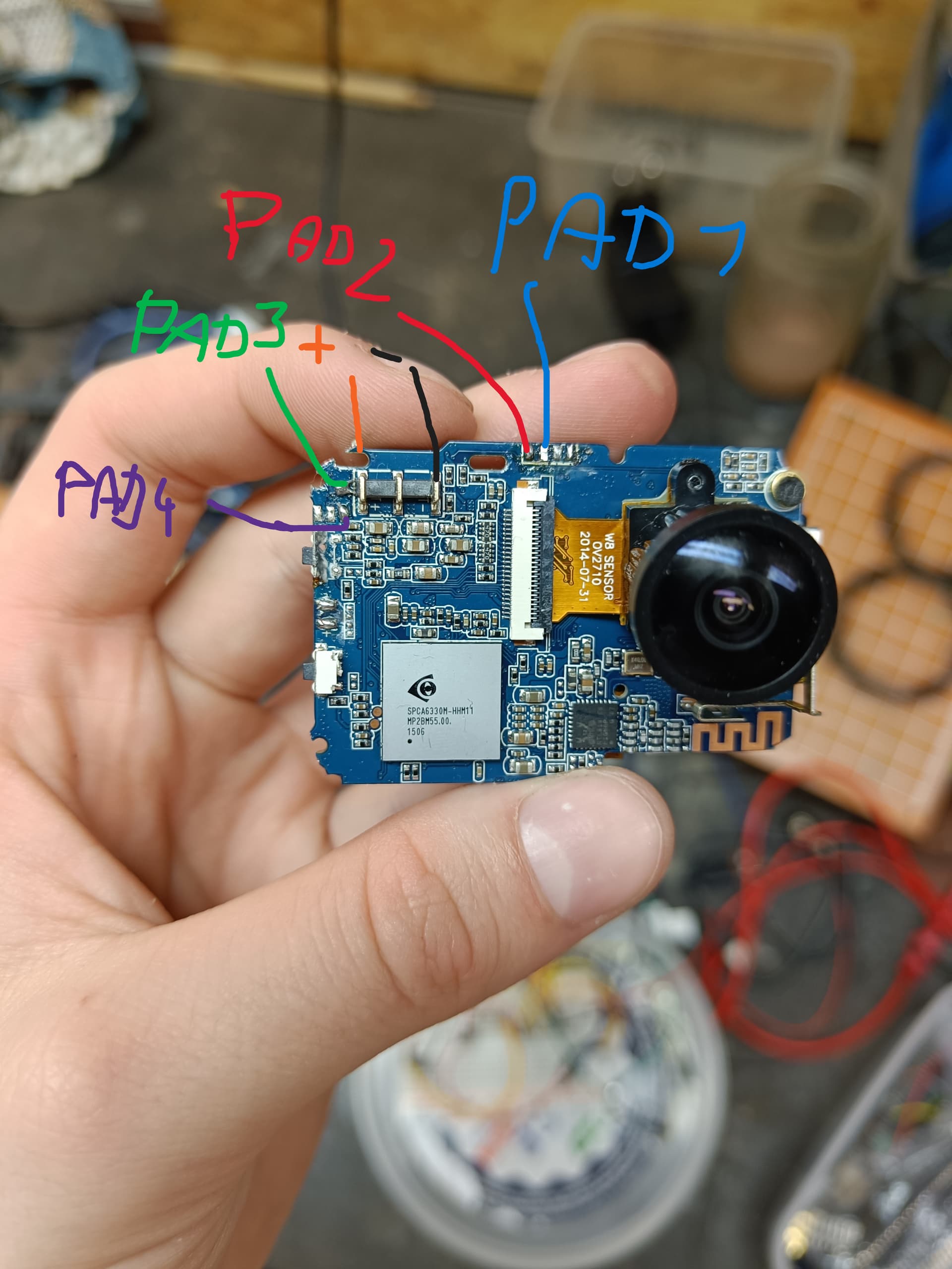
This the photo of the camera. I turn it on by connecting pad 3 and 4 for 3 seconds at least. To start the recording I need to connect pad 1 and 2 together for a split of a second. There are also two other buttons on the camera and one is broken but I don't need them to just start the video recording. So I should just meassure voltage across pad 1 and 2?
yes, measure across pads 1 and 2. This will probably show a low voltage like 3.3 volts, what matters more is that you identify which is positive with respect to the other so the current the switch woukd normally allow to,flow is routed the right way through the NPN transistor or, for that matter, the equivalent to an NPN transistor that is in the optoisolator.
If you went with a MOSFET, at no particular advantage here, you would still need to determine the
polarity with the same measurement.
It is possible, perhaps probable, that the negative of the two switch pads is actually also the ground level for the camera electronics. Until you know for sure, there is a possibility for excitement if the actual camera ground is different and some things come in contact that should not. Just keep the entire board free of any connections (advertent or accidental) between it and the rest of the world down to the two wires that are to jump the switch.
This is ann advantage of a relay or an optoisolator. Both provide a way to click the switch with no electrical path between anything on the camera side and anything on the Arduino side.
a7
Okay, I will tell u what I found out when I get home and measure the voltage. I am not quite sure if I understand ur third paragraph but from what I remember the pad 2 seems to be connected to the ground of the battery. Btw I will add that I need to press the buttons over a big distance (around 1km). I'm planning to use a HC-12 radio modules for sending string that will activate the push function. I have the stations with the communication over 1 km working but I don't know how to push the button with esp32.
Cool. First get the "I'm right here" button pressing going.
Then separately get a "I can count button presses that are coming from around 1 km away" sketch working - no worrying about any camera stuff.
Then you can combine known working functionality, no longer counting the button presses but making them tweak the camera.
a7
This topic was automatically closed 180 days after the last reply. New replies are no longer allowed.