I am essentially replicating this project where an Air Swimmer flying shark baloon can be controlled with an Arduino by soldering wires to the push buttons in the remote control and using transistors to control them with a signal from an Arduino pin instead:
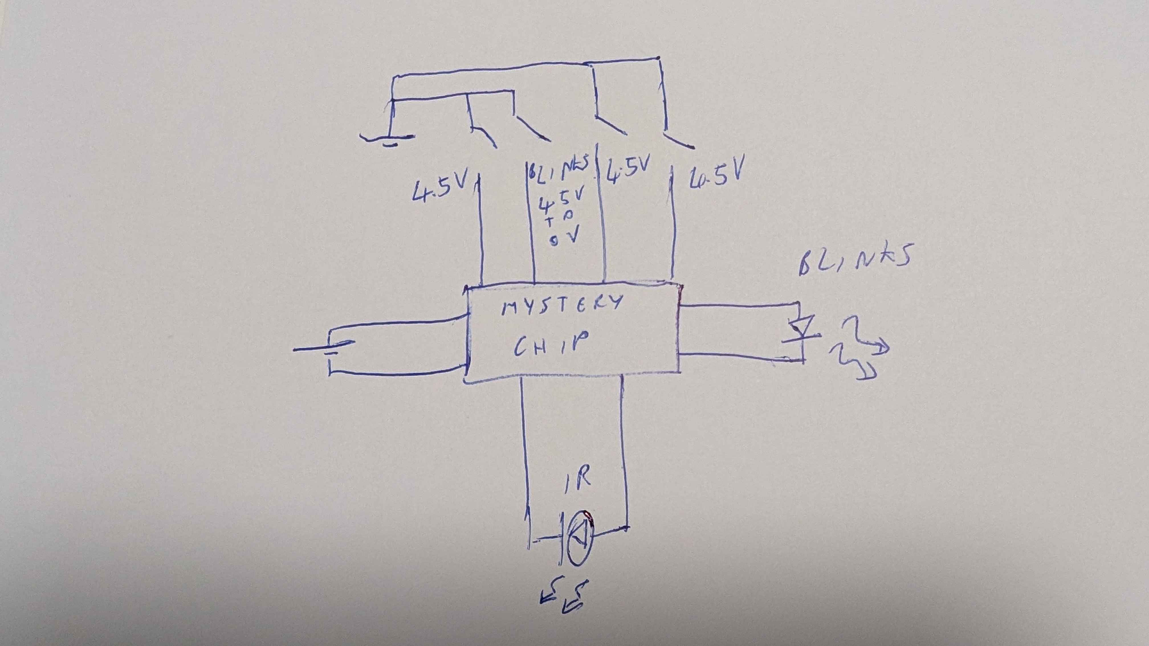
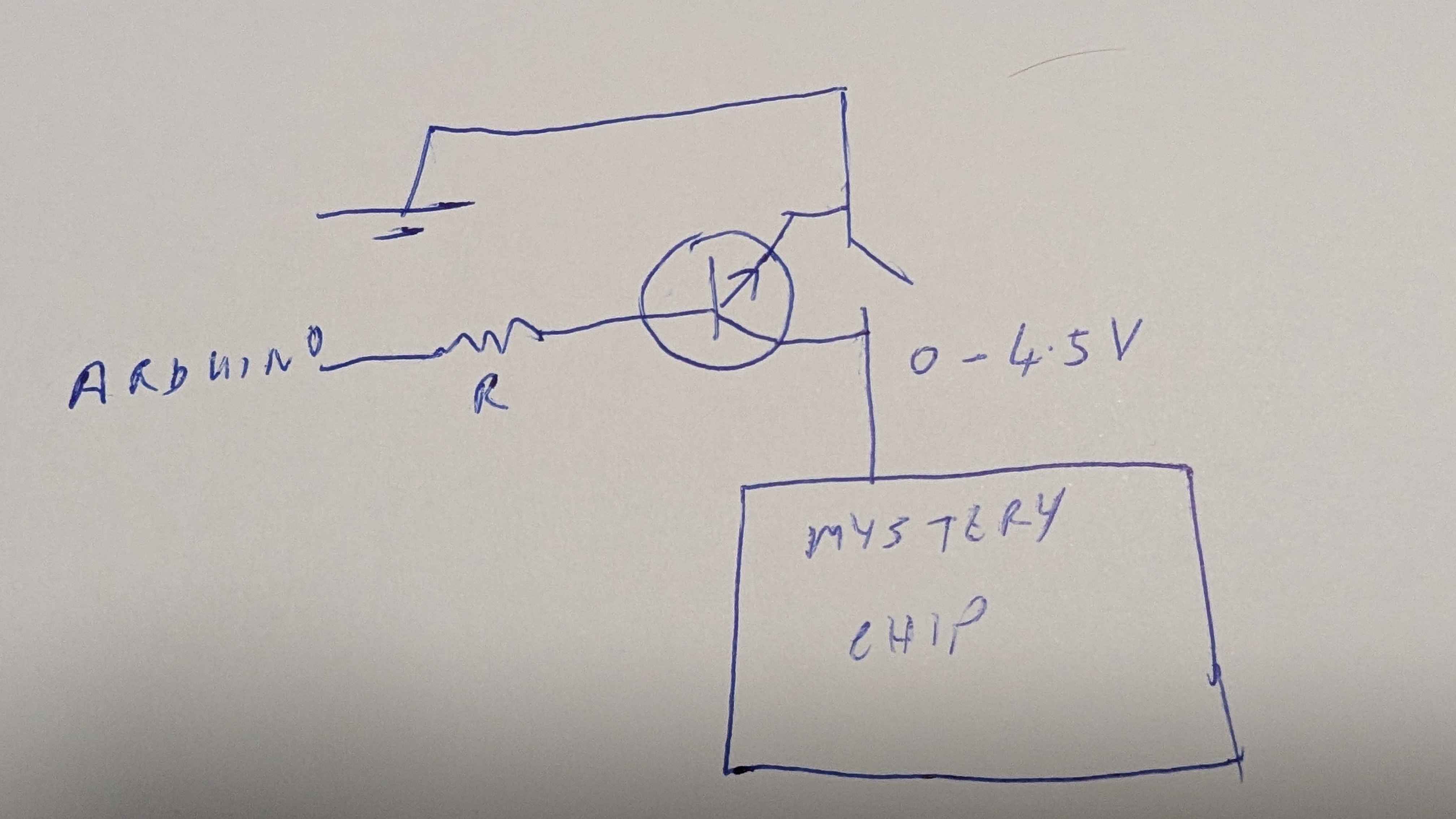
Each push switch controls a function when it connects to ground which sends the appropriate IR signal to the shark toy. And for most of them I can use an NPN transistor setup like this:
This works because the chip side of the switch is normally 4.5V (it is powered by 3AAA batteries). When I set the Arduino pin HIGH I can close the circuit.
However the connections from the chip one of the push buttons seems to fluctuate between 4.5V and 0V. This appears to line up with a blinking LED indicator light. I have no idea why this one switch is doing this, but it interferes with my transistor - which appears to permantly stay closed so the remote is constantly sending a signal to the shark (to swing the tail to the right).
Is there some way I can control this switch from the Arduino without it staying permantly on?
Use an optocoupler instead of only an transistor, to definitely separate the controlling system from the controlled one. This will also work with multiplexed buttons and LEDs.
Maybe you didn't connect the ground of the remote to the Arduino ground?
Not having a common ground could cause things to work perfectly, or partially, or not at all, depending on whether there's an 'R' in the month and what colour socks you are wearing.
(If you take the opto-isolator advice, you won't need a common ground.)
I do have a common ground. I also tried running the remote control from the Arduino 5V pin instead of batteries - to make sure ground was definitely the same - and I still get the same results.
I did check my solder joints and couldn't see any problems. If it was shorted I think I would have had even more problems.
An optocoupler does sound like an interesting option - I might look into that. Although the original article did have problems with them.
Would a PNP transistor make a difference? Then I would holding it closed with a HIGH signal.
I like alto777's suggestion. If it's not a code problem, I was just going to suggest replacing the resistors and transistors with relays, small ones like this: https://www.digikey.com/en/products/detail/coto-technology/9001-05-01/301690
Pay attention to the coil polarity because flyback diodes are built in.
I got a PNP transistor and it appears to be working. I didn’t have to wire them to the same power supply, but they are pretty close (4.5V battery vs 5V Arduino).
I did have to reverse the logic on one of the other buttons - I am not sure why. Although they could be related (swinging the tail right was the problem button and I had to reverse swinging the tail left)