Hi everyone, I'm a beginner to arduino and electronics and it's my first time posting.
I'm trying to do PWM on a series of high power UV-LEDs, regulating the current using a constant current source, and doing PWM using a NPN transistor. The issue I'm running into is since I added a transistor to the circuit that I turn on and off using an arduino, it turn's on and off like normal up until 9.4 volts, but to get to the full current at 10 volts, the transistor no longer fully shuts off.
Without the transistor, the supply voltage is 4.5 volts with a 3V drop across an LED. The current is 60 mA (although LEDs are spec'd at 700 mA for full power).
After trying to incorporate the transistor (PN2222A) for PWM, the voltage required increases significantly to approximately 10V. Up until 9.4 volts, the code works perfectly to do PWM on the circuit, but it only has a current of 30 to 40 mA rather than the full 60 mA. After increasing the voltage to 9.5 volts suddenly makes it so that the circuit no longer turns off from a simple blinking program. The current decreases though from 60 mA to 40 mA (rather than going to zero).
I think that it may be a problem with the rating of the transistor, but not certain what about it is out of spec. Any thoughts you have on this would be much appreciated. Also let me know if you have any questions.
So you would recommend that I use that MOSFET transistor instead? Do you have any guess at the reason for the NP2222a not working beyond a certain voltage? The mosfet that was recomended has a current and voltage threshold of 36A and 100V (drain to source), but the 222a has 800 mA and 40V so it seemed like it was within the operating conditions.
regulating the current using a constant current source, and doing PWM using a NPN transistor.
I'm guessing you don't really have a constant current source.
If you are using a (high-power) resistor as a current-limiter (like with a regular 20mA LED), then you can use PWM directly, or through a transistor/MOSFET.
Normally, there is a MOSFET or transistor (along with an oscillator and inductor) as part of a switchmode constant current supply. ...If you add another MOSFET/transistor for PWM, the constant-current supply gets messed-up and the voltage goes way-up as it tries to push constant current through a transistor that's turned-off.
Sometimes a constant-current driver can be PWM controlled, but it's just a low-power control-signal into the constant-current circuit. (That depends on the design of the constant-current supply.)
The thing is though, even when I tried to set up a 1 second ON/OFF blinking circuit instead of PWM, the light stayed on (even though the current did decrease). -
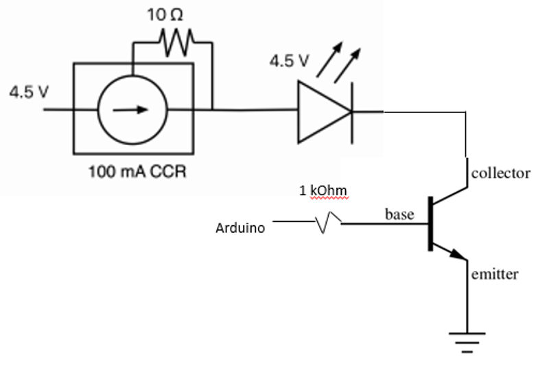
Also, I've attached a circuit, sorry it looks like it was drawn by a 2 year old in paint, I don't have a camera for a hand drawn circuit.
TomGeorge:
You have got the gnd of the power supply for the LEDs, connected to the gnd of the Arduino?
Hi Tom, thank you for the help on this, I totally missed the fact that the CCR that I attached had a very similar circuit for what I was doing. I have the ground of my arduino connected to the ground of my power supply, but I'm missing R2 from the diagram that you've attached, so I'll have to add that in.
TomGeorge:
A logic level MOSFET will be more efficient.
It seems like after comparing MOSFETs to BJTs, the MOSFETs are more efficient, but I still don't understand why the 2222a wouldn't work for this application, given that the diagram you pointed out has a similar BJT (NSS40201L) from what I can tell. I may be misunderstanding how to read the specifications on it though.
Hi,
Try adding R2, I doubt that it will make any difference,but keep the 1K, you need to saturate the transistor to get full current to flow through it.
If you take the the base resistor connection off the Arduino and connect it to 5V instead of the PWM , do you get the same brightness as PWM at 255?
Then connect the same resistor to gnd to see if the transistor switches OFF.
What voltage do you get at the collector of the transistor in either condition.
Also double check the transistor connections, there are 2N2222 and 2N2222A, they have different pinouts.
I can't think of any reason it won't turn off unless the transistor is bad/blown or unless it's wired wrong.
It should work without R2. You might try a lower value for R1 (maybe 1K) to turn the transistor on "harder" for more current when it's on. (Changing R1 won't help with the turn-off problem.)
I have the ground of my arduino connected to the ground of my power supply,
And the transistor emitter is also connected Arduino ground?
R1 should be 150 or 220 ohms not an astronomical 4.7k, R2 then does nothing, lose it.
[ you want to saturate the switching transistor, not "sort of turn it on a bit". The 150 ohm
resistor then acts as a very capable switch-off speed-up resistor too ]
If you turn off the power , you should be able to test the transistor with a DMM on diode scale.
You can Google how to do that and find numerous Youtube videos.
TomGeorge:
Also double check the transistor connections, there are 2N2222 and 2N2222A, they have different pinouts.
Well, this was my problem it seems... Very noobish mistake, kind of embarrassing, had the transmitter and the collector mixed up in my actual circuit. I guess I figured I had it write because it worked initially for the lower voltages. Thank you all so much for the help in solving this problem, you all are great!
Well, this was my problem it seems... Very noobish mistake, kind of embarrassing, had the transmitter and the collector mixed up in my actual circuit. I guess I figured I had it write because it worked initially for the lower voltages. Thank you all so much for the help in solving this problem, you all are great!
Actually, it is not common knowledge that there are two flavors of 2N2222. Most people are not aware of it.
In general , only the professionals who have been in the industry a while are aware of it.
I was in the industry at least 10 years before I discovered the 2N2222A.