is there any way to generate PWM signal using DAC output where i can control frequency ,Duty and signal amplitude ,using esp32 with arduino ide?
thanks for helping
is there any way to generate PWM signal using DAC output where i can control frequency ,Duty and signal amplitude ,using esp32 with arduino ide?
thanks for helping
With PWM you can vary the duty and frequency. If the PWM output is filtered, then the PWM duty value will control the amplitude of the filterwed output.
Here's how you can control the ESP32's DAC outputs.
That is a little strange. Usually whenever variable DC voltage or PWM is used, the other isn't necessary. Why do you need this?
Particularly, because in general, this feature is not provided on MCU's.
You can "fake it" by feeding the DAC the waveform that you have in mind, as suggested above, you are free to send it any waveform at all. Sometimes known as an "ARB". But you have to support it yourself in software, the MCU has no special hardware to do it directly.
Sure, but why? What does it do? Top secret?
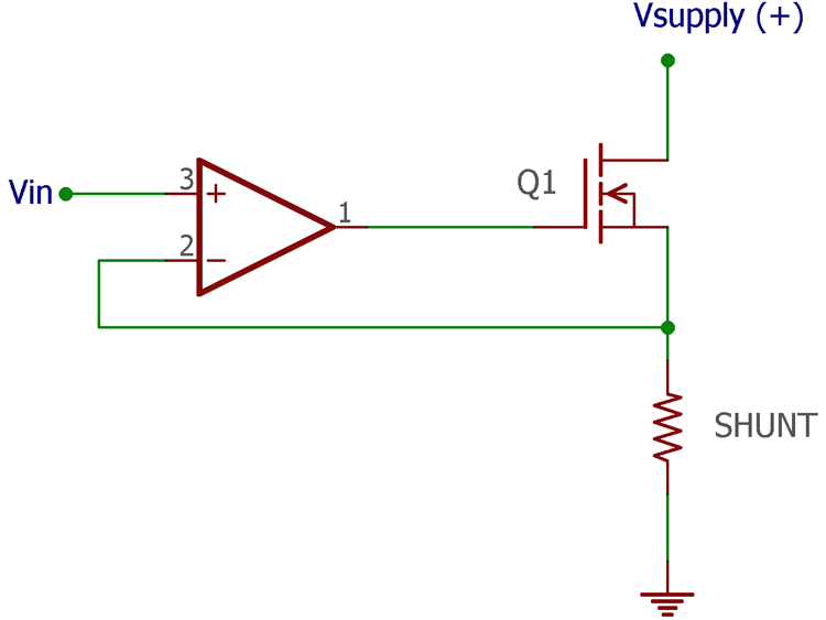
The circuit you posted isn't a practical circuit, I hope there is more to it than that, although the basic voltage controlled current stage with load sensing feedback concept is correct.
Well I'm trying to build circuit that can test and charge different type of batteries ,there is two function ,dummy load and charging circuit .
Yes, strange: a DAC or a PWM signal?
DAC converts digital sample values to analog out (a waveform).
PWM is modulated by varying the pulse duration, the signal is still a digital signal.
With an external RC circuit (filter) - it can be "converted" into analog.
Or use PWM in combination with a PWM Amplifier - called "Class D Amplifier".
You want to charge a battery with PWM?
"hmmmm" : are you sure your battery would like to see a full voltage with max. current for a period of time?
A PWM does not control a voltage: it is digital and switches voltage just on and off. You seem to "abuse" you battery as an "integrator", to filter PWM. But a good battery will still see the "PWM" with max. voltage (and max. current) for the pulse duration. If this is good for a battery?
Often, a battery charger is like a "constant current source" (the voltage follows the battery charging state). At a certain point when you see voltage over batter as "full" - you stop charging.
With a PWM directly on a battery - you do not get a constant current - instead: a very large one when pulse is on.
well just tryed ask chat gpt ,give me this code for arduino due 
#include <DAC.h>
#include <Wire.h>
#include <LiquidCrystal_I2C.h>
#include <Encoder.h>

const int dacPin = DAC0;
const int frequency = 1000;
const int resolution = 12;
const int amplitude = 4095;
const int dutyCycle = 50; // in percentage

Encoder myEnc(2, 3); // assign encoder to pin 2 and 3
int16_t encoderPos;
int amplitudeValue;

LiquidCrystal_I2C lcd(0x27, 2, 1, 0, 4, 5, 6, 7);

void setup() {
  // Initialize the DAC
  DAC->CTRLA.reg = DAC_CTRLA_ENABLE | DAC_CTRLA_CH0EN;
  DAC->CTRLB.reg = DAC_CTRLB_CHSEL_CH0;
  DAC->EVCTRL.reg = DAC_EVCTRL_STARTEI0;
  DAC->DACCTRL[0].reg = DAC_DACCTRL_ENABLE | DAC_DACCTRL_CCTRL;
  DAC->DACCTRL[0].bit.CCTRL = 0x3F; // Use the full range of the DAC
  DAC->DATA.reg = 0;

  //Initialize the encoder
  myEnc.write(0);
  amplitudeValue = amplitude;

  //Initialize the I2C LCD
  lcd.begin(20, 4);
  lcd.clear();
  lcd.print("DAC Amplitude:");
}

void loop() {
  encoderPos = myEnc.read();
  if (encoderPos != 0) {
    amplitudeValue = constrain(amplitudeValue + encoderPos, 0, amplitude);
    lcd.setCursor(0, 1);
    lcd.print("               ");
    lcd.setCursor(0, 1);
    lcd.print(amplitudeValue);
  }

  for (int i = 0; i < resolution; i++) {
    if (i < resolution * dutyCycle / 100) {
      DAC->DATA.reg = amplitudeValue;
    } else {
      DAC->DATA.reg = 0;
    }
    delayMicroseconds(1000000/frequency/resolution);
  }
}
i dont know if it will work or not
Do you want to generate an analog out (via DAC) or a PWM (digital)?
Two completely different topics.
It looks like you try to use a DAC in order to generate a PWM (digital) waveform.
OK, possible (for low frequencies), but why so complicated (convert digital to analog - analog to digital)?
Are you sure your DAC is fast enough for such a (digital) waveform? (I am not.)
I guess, you have to think about what do you want to accomplish and then look for the right means to implement (and simplify the system: "why a DAC in order to generate a PWM?" A PWM peripheral can do, even a GPIO pin can do, but a DAC would "filter" your digital waveform and it will NOT look "perfect". The SW to do is way to complicated).
MCU is digital - remain digital as long as possible. A DAC is the output to external world as analog. But PWM is digital - WHY a DAC?
If you are not keen on using a PWM device - toggle a GPIO pin. 
You can feed the PWM signal as a reference to a DAC that will then control the amplitude
I think "you are lost".
Sure, I can control a DAC with amplitude swings like 0V and VDD volts. So, I "try" to generate a digital signal again, on analog out (after the DAC).
But if you understand "your DAC":
I am pretty sure: a DAC cannot generate the same fast digital signal as you would be able to generate via a PWM or GPIO pin.
The DAC is already a "low pass filter" and the digital signal will look ugly (wrong slew rate, long raise and fall times on rectangle signal, passing just a low frequency ...).
A DAC is for analog out signals.
When creating a digital signal with a DAC - check the Shannon Theorem (Nyquist Criteria):
generating a "nice" digital signal again - needs a very high bandwidth (and the DAC does not provide, it is a "low pass filter").
A rectangular edge on a digital signal needs unlimited (very high) bandwidth (frequencies). The DAC does not provide, for sure.
Good luck with using a DAC for a digital signal generation (what a "crazy idea").
(it works fine in range of Hz - but not with KHz, and even just if you would accept a large slew rate with any frequency ...).
I agree. I think the OP is chasing faeries.
@Fouad19764 - you will ned to explain in a LOT more detail what you are trying to achieve and how you hope to do it. If you are interested in building a circuit to test and charge batteries please refer to this thread