I made a buck converter with an Arduino that tries to keep the INPUT voltage constant. The input is a solar panel.
Every 5 minutes, the programme stops and checks the open circuit voltage to adjust accordingly.
After approximately 8 minutes, digital pin 6 (connected to the mosfet) stops working. It outputs 40 mV (practically 0) independent on the stated duty-cycle (even if it sais that it is giving it 200 out of 255, it still outputs a very small voltage).
When it does this, it is in the "void loop" part of the code.
What can I do?
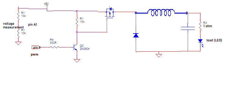
Your schematic shows only a small portion of your circuit. Please post schematics for the entire system, so that we can gain a full understanding of the operation of your mostly undocumented code.
Assuming "+9" in your schematic is the buck converter output, the remainder of the circuit appears to just turn an LED on and off. I happen to know that it's probably an optocoupler, but most people wouldn't get that right away.
Ok, thanks for that updated diagram and code, it's very helpful. In future, though, please don't edit previous posts, as it makes the replies seem like nonsense.
May I ask, how are you measuring the PWM voltage? A DMM can't read such signals accurately.
Your schematic/wiring diagram is still incomplete, the code references A5 and you have shown no connection to it.
Also, why do you use an ADC scale factor of 1023 in some places and 1024 in others? Can't make up your mind?
Are you trying to make a Maximum Power Point Tracking MPPT charger?
You cannot regard a PV as a voltage source like a battery, it is a current source and behaves completely differently.
Can you tell us what you want to control, the input voltage or the output voltage.
Thanks.. Tom..
PS. Forget about using that sort of CAD, the best CAD is an image of a hand drawn circuit.
Its faster and you don't have to try and draw fiddly zigzags and curlies with a mouse.
Please label pins as well, especially the MOSFET and put its part number on the diagram.
Yes, using multimeter to measure pwm voltage. From my testing, it shows accurate readings on pwm (it also sais that is measures "true rms").
Multimeter shows almost 0V on pin 6 and mosfet is OFF, thus the voltage actually is 0V.
A5 is connected to ground, ignore it.
Good point. I was not consistent. But, I don't think this will make my code stop working
Edit - I'm guessing you are thinking, "but, I just want to fix this one problem". That may be possible, but you still haven't really given us everything we need to help with that. The things that we are asking which may seem unrelated, are actually a direct result of having to guess so many things about your project.
If you do not range check your pwm value after these calculations, it can go outside the expected range of 0-255. For example, say your current pwm = 254 and voltage_in > voltage_target which means the else() clause get executed, setting pwm = 257
HI, just measuring the open circuit voltage of your PV panel will not give you its most efficient working load, that is max output power for the prevailing conditions.
Thanks, man! "the best CAD is an image of a hand drawn circuit"
I looked at my original circuit design and saw that I had connected the diode wrong. The inductor could not "discharge" during the OFF period, thus creating negative voltage spikes. I guess the arduino didn't like the surges in potential, and would stop working after a couple of minutes.
After fixing the circuit, it works well.
I know the theory of MPPT (or at least I think so). I measure the open circuit voltage and then attempt to reach 75% of that (I tested and 75% is best for my panels).
@blh64 Thx for pointing that out (the part with pwm=257). I will fix it.