I have a Mega project which is using PWM on 3 of the pins, to drive needles on some vintage-looking gauges.
I also have about 20 pins on the Mega that are dedicated to blinking some LEDs via "digitalWrite(pin, HIGH)" and "digitalWrite(pin, LOW)". Most of the other Mega pins are connected to 7-segment displays, WS2812b strips, some toggle switches, etc.
My Mega is powered by a power supply that I plugged into my wall outlet and is sending 12V to the VIN pin of the Mega. It also sends 12V through a buck converter to get it down to 5V, from which most of the items above (7-segment display, WS2812b strips, etc.) are powered.
When I have those 20 LED pins just constantly set to HIGH, and my program moves the PWM pins from 255 to 0 over the course of about 10 seconds, the PWM indeed goes nice and steady from 255 to 0.
When I have those 20 LED pins blinking via randomly oscillating between "digitalWrite(pin, HIGH)" and "digitalWrite(pin, LOW)", the needles go from 255 to 0 but has a lot of jitters along the way. Even if I have the oscillations be pretty sparse, e.g. 500ms to 1000ms between blinks, this jittering still happens.
However, I have noticed that if I also plug a USB cable from my laptop to the USB connection on the Mega, the needle moves smoothly even when the LEDs are blinking. So this appears to not be a code issue, but a power issue.
Is it somehow the case that I am not sending enough power to the Mega via the VIN pin alone? Does a USB connection somehow enable better PWM functionality? Thanks!
The best way to power a Uno or Mega is with 5V via the USB jack.
Unfortunately, Arduino doesn't provide a way, simple or otherwise, to do that.
A simple thing, for me, is to hack a USB, fishing out the red and black wire. For others that's a near-herculean task.
Officially, (as you know?) Arduino says not to.
That's probably because they know bad things happen when people hurriedly set about to update and so on - and forget to undo that first.
It's hard to say for sure, but I think no more than 150mA being pushed out of the Mega in its various pins. I know for sure that about 100mA goes to the aforementioned 20 LEDs that are blinking. Most of my other stuff is powered directly from the power supply and I just use the Mega for the signal/data.
Ultimately this is for stuff I will have in a car, and I would like to power it via a small 12V marine battery. I guess I could use a USB power supply for the Mega and a marine battery for the rest of the stuff, but this is literally the only issue that is causing me trouble and preventing me from just using a marine battery for all power needs.
PWM just seems to be influenced by what else is in use or drawing current on the Mega, which is kind of a bummer.
The alternative route I am considering is to use a Nano just for the PWM to drive the gauge needles. I really only need to signals to the Nano for: (1) put the needles at full, (2) start a sequence to drain the needles. All of the logic for how exactly the PWM does those things can be on the Nano and this would be the only thing drawing current from the Nano so I think it would be more reliable.
For my purposes, when I say "VIN" I mean the pin on the Mega that is labeled VIN (actually I guess "Vin"). And for that one, too, the PWM seems to be influenced by other draws on it. I have never used the barrel jack on the Mega. For the USB jack, I think it can do the PWM without being influenced by other current draw.
The Mega board is equipped with a 1117 regulator for 5V. It sits on a copper lane of - roughly estimated - 10x15mm. The datasheet gives a max. dissipation of 1W or slightly above. At 12V input that means max 150mA. The CPU of the 2560 takes 20mA, the 16U2 USB interface 15mA, adding some small stuff on the board and about 50mA is needed even doing nothing. If the LEDs take 100mA, the 1117 is on the brink of thermal shutdown.
Two possible solutions:
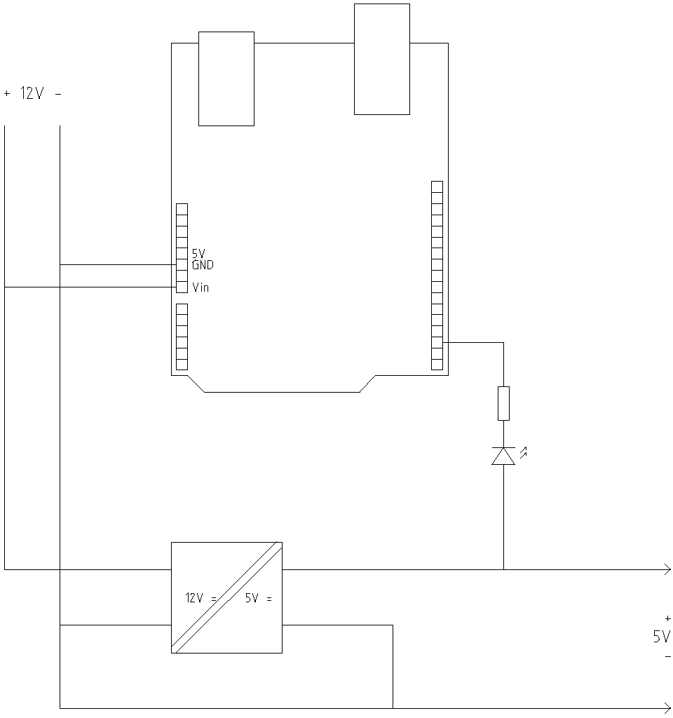
1: Switch the LEDs negative, between external 5 V and the outputs, keeping the board supplied with 12V at the Vin pin.
2: Supply the external 5V into the 5V pin, but mind decoupling.
I believe I moved the Vin connection from the pre-buck-converter 12V for the purposes of this whole PWM needle thing; it improved something a while ago, and I am not sure why it did but I figured I would stick with that setup since the Mega could accept 12V. However I did not have any idea about this Mega regulator, nor how close (or past) its heat limit I was.
And indeed, when I switch the Vin pin to connect to post-buck-converter 5V, the needle jumping problem is solved! Thank you both so much for your help!
Just to learn as much as I can here, I have a couple of follow-ups if I can ask a bit more of you
Are you saying I connect the long side (electricity in) of the LED to my power supply, and the short ground side to the Mega pins... and then use digitalWrite(pin, HIGH) to essentially block electricity flow, and digitalWrite(pin, LOW) to allow electricity to flow from the power supply, through the LED, and into the Mega to ground? This makes a lot more sense if it works but figured I would ask if this is what you meant before I tried it.
(Also to your other question, yes I am familiar with millis(), thanks to some helpful folks in my first thread on this forum about 8 months ago).
When I have them set to digitalWrite(pin, HIGH), they are drawing current to be lit up. If I am understanding correctly, you might be getting at what stitech was suggesting with swapping that functionality so the LEDs get current directly from the supply?
I think you're right, good point! Honestly I just assumed 12V would be easier to find because of car batteries and stuff. But since I power some LED stuff directly from the power source, I am guessing I should still find a converter to convert the 6V to 5V (rather than my current 12V to 5V) before stuff gets connected to it?
Your first picture looks like how I have things set up now. I am a little confused about the second one though. Can you spell out the difference between the Vin and 5V pins? I just don't follow why that matters. And what are the 470u and 1R notations for?
Regarding the car battery, I am also looking into some exterior LEDs, which take up a lot of current I believe. So if I went to a car show or something that lasts a few hours, I could see it draining the battery pretty heavily and risking the headache of needing a jump at the end of the event. I just figured a separate battery would help ensure I didn't add additional problems to the car itself. I am still quite new to this so having as many systems isolated as I can, should help narrow down the list of potential causes when something goes wrong (with the car, or the lights/Mega/etc.)
The Vin pin leads to the regulator. Possible spikes and noise will be regulated away. But: the input of the regulator needs to be sufficiently higher than the desired voltage, or the regulator can't regulate. In that case the input voltage will be passed through, losing more than 1V, while all the noise also passes through.
The output of the regulator is connected to the 5V pin and the supply pins of the chips. The board contains some decoupling to suppress spikes and noise, and it's possible that that allows the system to operate just fine. I added an extra filter, better safe than sorry. The 1 Ohm resistor is a wild guess, the filtering will be better with a bigger resistor, but there will be more voltage drop (a few tenths of a Volt is no problem, you'll lose that anyway when supplied from USB).
About the car battery: apparently you already thought about that.
Thank you for that detail on the difference between those pins! As you can maybe tell, the only things I only know about the Arduino are from tutorials I've looked up for the specific things I have done so far. Most of the LEDs and digit display stuff "just work", regardless of the electrical source, as long as it's around 5V... so I got a bit complacent and didn't really need to worry about how it was all hooked up. The PWM thing was the first time it really seemed to matter and so I clearly had to catch up on all the stuff I ignored to this point about voltage variances based on pins and power sources.
Great site! It covers a lot of things I have been learning about with my projects. One thing I will mention though - you say:
... but as far as I can tell, you don't say what those are I am guessing an advantage to the second one is less current being sent out of the Arduino, which is good because it does have an upper limit to that. And maybe an advantage to the first one is that the ground line stays free of current and there is less risk of an accidental short causing the LED to burn out? I am sure there is more I am not thinking of.