Hello,
I am trying to generate a PWM on a digital pin to drive a continuous rotation servo with an Uno, however, when I scope the signal coming off the pin, the wave is squarish but fluctuates pretty wildly. I have checked the oscope using the onboard reference and it shows a near perfect 1 kHz square wave. I can not get the servo to work with either a PWM, or using the servo library. It does not move at all. I am powering the servo with an external 6 V power supply, so I don't think it is driving the arduino to reset. I am not sure if the problems are even related, right now I just want to see a "clean" PWM signal from the arduino. I have tried several different PWM pins, as well tried using analogWrite(), and I have tried it with all three grounds on the Uno. Any ideas on what is going on here? Am I missing something stupid and easy? I have seen a good square wave from a PWM signal on this scope with the same Uno before, so I don't know what has changed. The output of the oscope is attached.
Here is the code I am using to generate the PWM, for the sake of completeness:
I can not get the servo to work with either a PWM, or using the servo library.
I'd suggest you get the servo working first with the servo library just to verify your wiring and power setup are appropriate. Attached is how to externally power the servo. The below code might help you setup your continuous rotation servo.
// zoomkat 3-28-14 serial servo incremental test code
// using serial monitor type a character (s to increase or a
// to decrease) and enter to change servo position
// (two hands required, one for letter entry and one for enter key)
// use strings like 90x or 1500x for new servo position
// for IDE 1.0.5 and later
// Powering a servo from the arduino usually *DOES NOT WORK*.

#include<Servo.h>
String readString;
Servo myservo;
int pos=1500; //~neutral value for continous rotation servo
//int pos=90;

void setup()
{
  myservo.attach(7, 400, 2600); //servo control pin, and range if desired
  Serial.begin(9600);
  Serial.println("serial servo incremental test code");
  Serial.println("type a character (s to increase or a to decrease)");
  Serial.println("and enter to change servo position");
  Serial.println("use strings like 90x or 1500x for new servo position");
  Serial.println();
}

void loop()
{
  while (Serial.available()) {
    char c = Serial.read();  //gets one byte from serial buffer
    readString += c; //makes the string readString
    delay(2);  //slow looping to allow buffer to fill with next character
  }
  if (readString.length() >0) {
    if(readString.indexOf('x') >0) {
      pos = readString.toInt();
    }

    if(readString =="a"){
      (pos=pos-1); //use larger numbers for larger increments
      if(pos<0) (pos=0); //prevent negative number
    }
    if (readString =="s"){
      (pos=pos+1);
    }

    if(pos >= 400) //determine servo write method
    {
      Serial.println(pos);
      myservo.writeMicroseconds(pos);
    }
    else
    {
      Serial.println(pos);
      myservo.write(pos);
    }
  }
  readString=""; //empty for next input
}
Sorry about that Everybody, I had to step away from it for a while, but I am back at it now. I will do my best to reply to everyone with the results of what I have tried based on your suggestions.
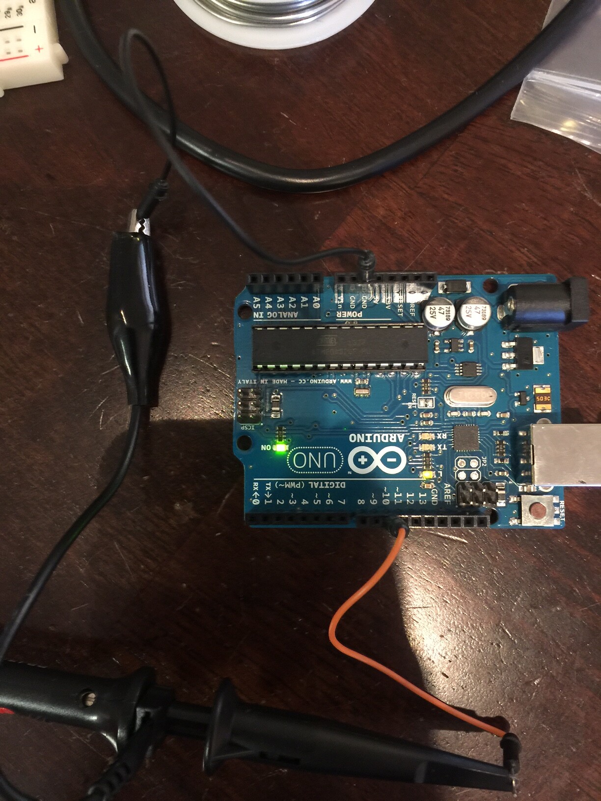
WAWA: The picture is attached. It is just the setup for reading the PWM signal from digital pin 10.
DVDdoug: No, the 5V is not solid, it shows the same "waviness" characteristics of the PWM signal when I scope the 5V output on the UNO. Thank you for pointing out the timing issue, I have corrected it.
Zoomkat: I also tried using the servo library, my understanding is that after attaching if you use servo.write, you are still sending a PWM signal to the pin. When I scope the pin using the servo library I get the same strange wavy PWM. Also, when I try to run the servo with either method, nothing happens.
TomGeorge: As you can see from the picture of the setup (that I admittedly should have included in the first place) the CRO probe ground is connected to the arduino.
Hey everyone. I am happy to report that the problem is solved thanks to my 3 year old son. I went to the bathroom and he managed to get a hold of my wire cutters which he promptly used to cut the cord on my CRO probe in half. While this in itself was not so good it did force me to use a different probe to continue troubleshooting, which, it turns out was the problem. Apparently the first probe I was using had a bad ground in it, as soon as I connected the second probe I got a perfect square wave. I probably (definitely) should have tried that a lot earlier, so we will chalk that up to tunnel vision. Thanks to all of you for your input and help, and thanks to my son and wire cutters...
Zoomkat: I also tried using the servo library, my understanding is that after attaching if you use servo.write, you are still sending a PWM signal to the pin. When I scope the pin using the servo library I get the same strange wavy PWM. Also, when I try to run the servo with either method, nothing happens.
Hey everyone. I am happy to report that the problem is solved
Just curious, does the servo still not move, or did fixing the scope probe fix the servo issue?
zoomkat:
Just curious, does the servo still not move, or did fixing the scope probe fix the servo issue?
The servo issue was completely unrelated, I forgot to hook the ground of the arduino to the external power ground. So, that problem is also now resolved. The servo turns and responds well to changes in the pulse width. Now I am off to port the code to LabView (ugh) and figure out a way to keep the servo from jumping that tiny bit when power is first supplied to the board. Thanks for all the help everyone. I will be sure to hide the wire cutters...