Hello
i try to build a plug for my heatingmachine. I found some wiring cricuit and i tried to remake this.
Know i want understand the wiring. Can you help me?
Here is a picture:

My basics:
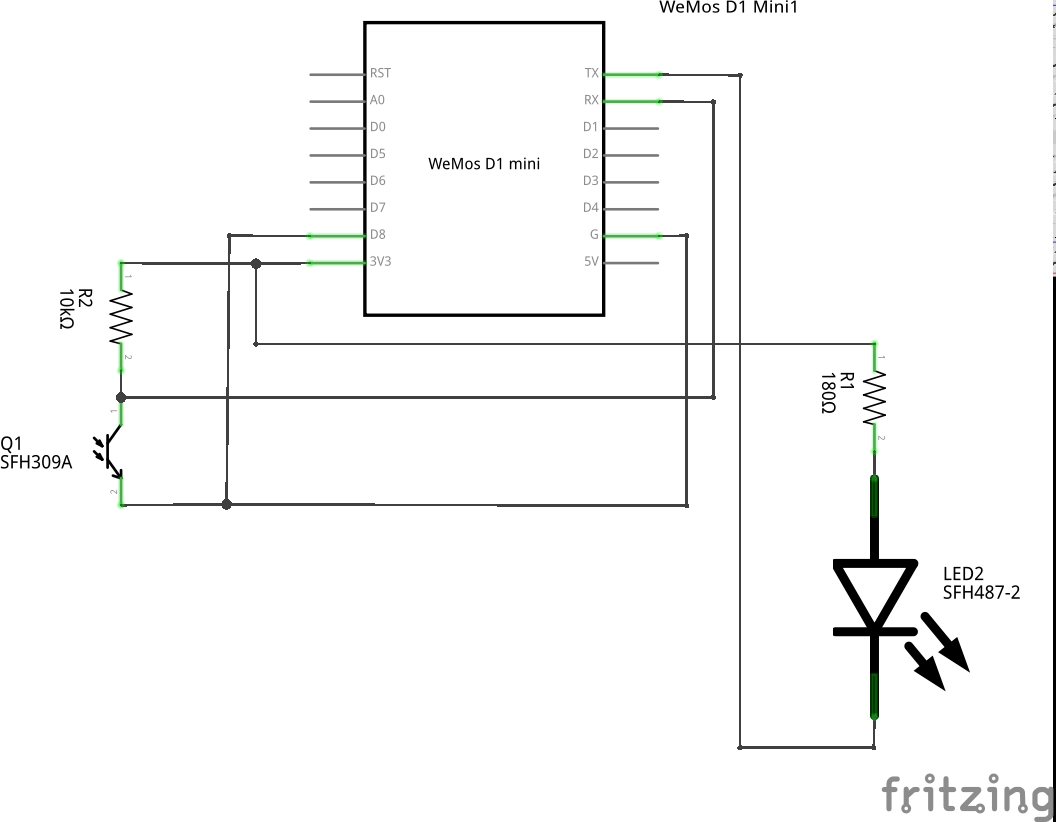
Rx get some data to the esp
Tx send some data from the esp
so i use two IR Sensor. One send data, the other want get/read data
the TX sensor:
is powerd by 3.3v with a 180ohm resistor. i will use 220ohm. the resistor set the senibility higher...
The cathode is connected to the TX pin. It will send the data.
WHY ISN'T here any connection to ground?
the RX sensor:
is powerd by 3.3v with a 10k ohm resistor. the resistor set the senibility higher...
the cathode is connected to ground.
WHY IS IT CONNECTED WITH D8????
What daoes the D8 pin do???
thank you for your help!